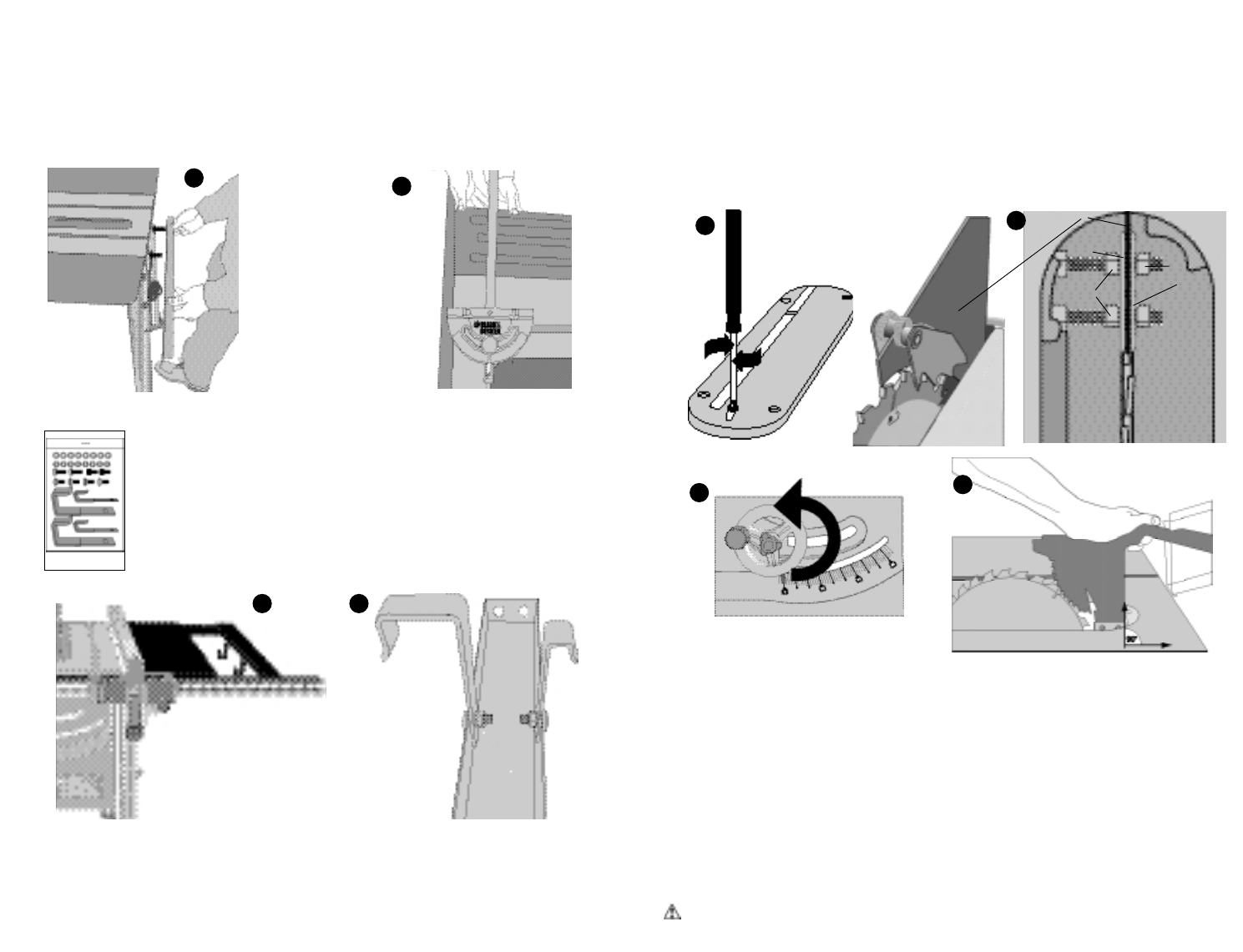
guard clamp nuts (D) which changes the location where the spreader mounts. Make sure
the spreader is centered and parallel to the blade by lining up the parts with a straightedge.
Also make sure there is some clearance between the spreader and the blade and that the
blade spins freely. Using one hand to keep the spreader straight up and down as shown
in Figure 23, tighten nuts (A) with 10mm wrench supplied, lower blade and replace throat
plate. If the spreader is not parallel to the blade up and down, simply bend it left or right
until it is aligned with the blade at the top and bottom when the blade is at the full upright
position. IMPORTANT: THE GUARD SHOULD BE IN PLACE FOR ALLPOSSIBLE CUTS.
When making non-through cuts, the guard can be easily removed by slightly loosening the
outer guard nuts (A). The guard can easily be replaced without having to readjust the inner
nuts.
Adjustments
PERFORM ALL ADJUSTMENTS WITH THE TABLE SAW UNPLUGGED.
NOTE: Your table saw is fully and accurately adjusted at the factory at the time of manufac-
ture. If readjustment due to shipping and handling or any other reason is required, follow the
steps below to adjust your saw.
Once made, these adjustments should remain accurate.
STEP 1. Checking the throat plate
To change the height of the throat plate, loosen the phillips head screw in the front of the
throat plate and adjust the four setscrews on the throat plate with a 2.5mm hex wrench.
When properly adjusted, the front of the throat plate should be flush or slightly below the
surface of the table top, and the rear of the throat plate should be flush or slightly above
the table top.
CAUTION: The table insert must be in place and securely fastened at all times.
STEP 11. Attaching rear rails (Figures 16,17)
From the rear of the saw attach the longer rear rail to the left side of the tabletop (Figure
16) using three capscrews with lockwashers. NOTE: The capscrew that attaches to the
table extensions will also require a hex nut (from table extension hardware bag). Using the
miter gauge as a straightedge (Figure 17), level the outside edge of the table extension
and tighten the two outside capscrews on the left side rear rail. Repeat the process for the
other side extension. Level the two rear rails where they meet and tighten the two cap-
screws in the center of the tabletop.
STEP 12. Attach right side table brace (Figures 18,19)
The table brace fits between the rear rail and the front rail as shown in Figure 18.
It also serves as a convenient place to hold the miter gauge and rip fence when
not in use. Assemble the brackets to the brace as shown in Figure 19 before
attaching it to the rails. Use four round head carriage bolts, lockwashers and hex
nuts from the fence and miter gauge storage hardware bag shown to the left.
Insert two square head bolts into the channel of the front rail and attach the brace
to the rail using two lockwashers and hex nuts. Use capscrews to attach the rear
end of the brace. NOTE: The large brackets are for rip fence storage and are
located on the outside edge of the brace.
STEP 13. Install the guard and spreader assembly (Figures 20,21,22,23)
Remove the throat plate as shown in Figure 20. Lower the blade to tabletop height by turn-
ing the blade height adjustment wheel (front of saw) counterclockwise (Figure 21). Loosen
the outer guard retaining nuts (A), shown in Figure 22, enough so that the spreader will fit
between the two guard retaining plates (B). Raise the blade to its highest setting. Install
the spreader (C) and ensure that it is aligned with the blade and that the back edge of the
spreader is 90 degrees to the tabletop. If not, the position is adjusted by moving the inner
18 19
9
16
17
C
B
A
B
D
22
20
21
23