


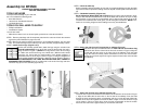
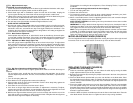

STEP 8. Aligning and leveling the front rail assembly (Figures 9,10)
Loosen the lock knob in the center of the front hand crank and turn the crank handle clock-
wise to raise the blade so that it is approximately two inches above the tabletop. Thread
the orange rip fence locking handle (part C) into the front of the rip fence (part B). Place
the rip fence on the front rail to the right side of the blade as shown in Figure 9. Slightly
push against the side of the rip fence and slide it over until it comes in contact with the
blade. With the rip fence in position, tap the appropriate end of the front rail until the 0
marking on the scale aligns with the line in the window on the right side of the rip fence.
(The left side will not line up until fence is on left side of blade.) Carefully lift off the rip fence
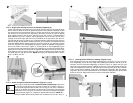
without changing the rail position. Now that the front rail is in position, it is important to level
it with the tabletop before tightening it down. To level the front rail, use the longer section
of the rear rail (part H) as a straightedge and place it against the tabletop and against the
front rail as shown in the insert in Figure 10. Pressing down on the straightedge (Figure
10) where the two rails meet will level the rails. Keeping the front rail firmly pressed down,
tighten the hex nuts with the 12mm wrench supplied. Now place the fence on the left side
of the blade to see if the pointer lines up. If not, loosen the phillips head screw and slide
the plastic piece to align the red mark. NOTE: Remaining four capscrews will be used in
step 11 to attach rear rail.
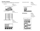
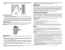
STEP 9. Attach the right and left table extensions (Figures 11,12,13)
Insert a square head bolt from the extension table hardware bag shown to the
left, into the channel opening at the end of the front rail as shown in Figure 11.
Push the table extension onto the bolt in the rail (Figure 12). Place a lockwash-
er and nut on the bolt and tighten snug but not tight. Insert three capscrews with
lockwashers into the edge of the extension and into the tabletop and tighten
snug but not tight (Figure 13). Repeat for opposite side extension. NOTE: Re-
maining hardware will be used to attach rear of extension to rear rail in step 11.
9
10
8
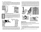
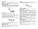
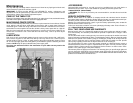
STEP 10. Leveling table extensions to tabletop (Figures 14,15).
Slide extension from the rear until it stops against the front rail (Figure 14). Lay a rear rail,
as a straightedge, across the back edge of the tabletop and extension and lift up on the
extension until it is flush with straightedge as shown in Figure 15. Tighten the rear most
capscrew of the extension with the supplied hex wrench. Lay the straightedge across the
front of the tabletop and extension and repeat the process of pulling up on the extension
until it is level with the tabletop. Tighten the remaining two capscrews. With the straight-
edge still in place, level the outside portion of the extension and tighten the square head
bolt in the front rail. Repeat this process for the left side table extension.
15
14
7
8
12
11
13