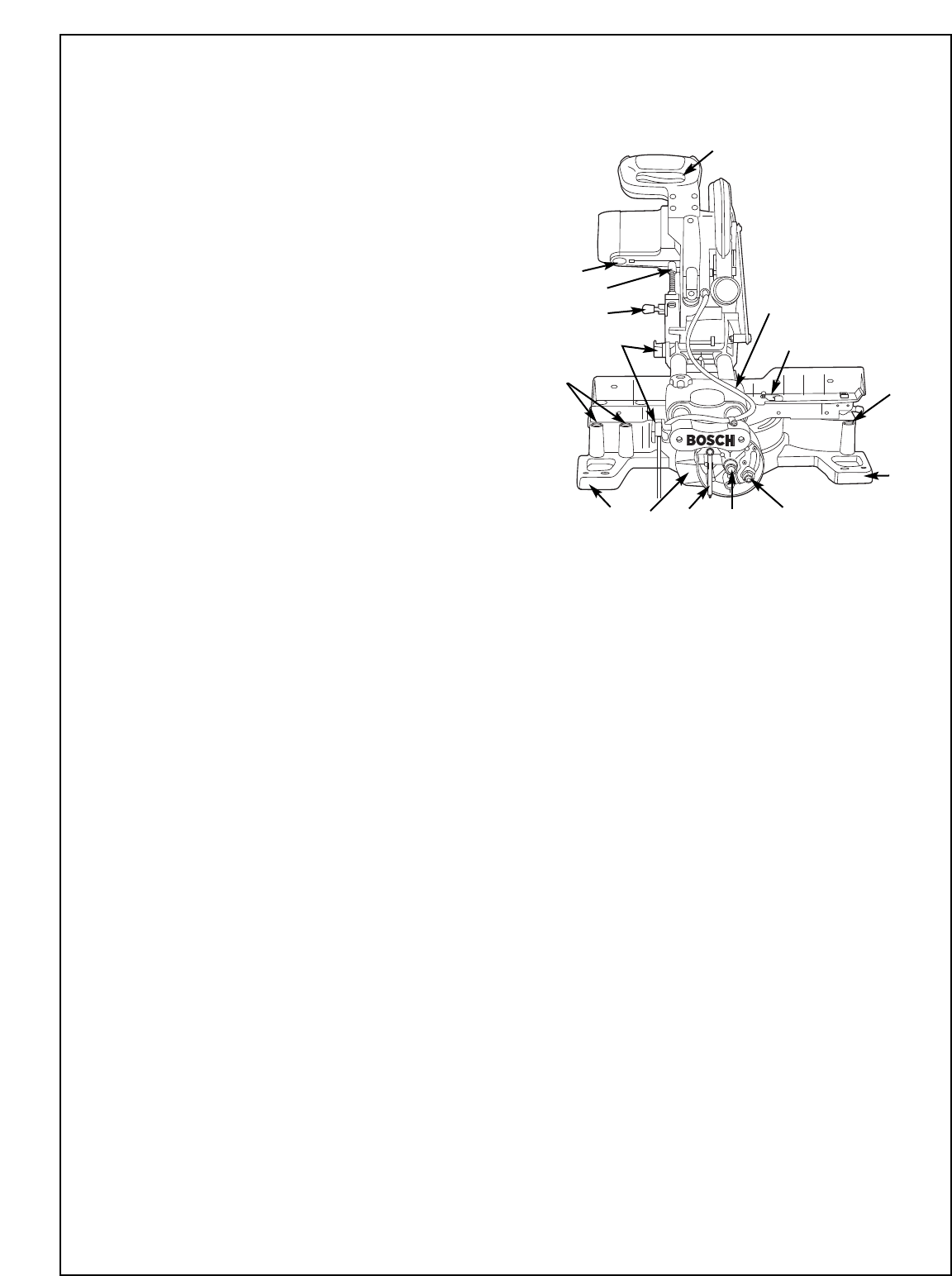
Getting To Know Your Miter Saw
10. Miter Lock Knob
The miter lock knob locks the miter saw table at any
desired miter angle.
11. Miter Detent Trigger
The trigger releases the table from the detent.
12. Miter Scale/Miter Angle Indicator
Scale is cast in on the base of the saw. Indicator is fas-
tened to the table.
13. Miter Detents
Ther
e are ten (10) miter detents for fast and accurate miter
cuts of common miter angles.
14. Table
Sits in base, provides workpiece support, rotates for desired
miter cuts and rotates the head assembly. The front extend-
ed part of the table is called the miter arm.
15. Base
Provides working surface to support workpiece.
16. Tool Mounting Pads
17. Base Extension Clamping Levers
Locks Base Extensions into place. One for each extension.
18. Extension Rods
Add support for long workpieces.
19. Sliding Fence
This provides extra support and clamping area for com-
pound miter cuts.
20. Sliding Fence Clamping Lever
Locks the Sliding Fence in place.
21. Chip Deflector with Dust Flap
This protects against large chips from entering the upper
guard.
22. Dust Chute Elbow
The dust chute elbow rotates 360° and can accommodate
the dust bag or a vacuum hose hookup.
23. 0° Bevel Stop
Adjustable stop for a quick and accurate 0° bevel index.
24. 33.9º Bevel Stop
Adjustable stop for a quick and accurate 33.9° bevel index.
25. 45° Bevel Stop
Adjustable stop for a quick and accurate 45
° bevel index.
26. Slide Rail Lock Knob
The slide rail lock knob locks the slide rails when you are
not making slide cuts and when you are transporting the
saw
.
27. Slide Rails
Guide the head assembly when making slide cuts.
28. Workpiece Clamp
Provides fast clamping of workpiece.
29. Lower Guard Actuation Link
Allows for smooth movement of the lower guard.
30. Upper Blade Guard
Covers upper portion of the blade.
31. Blade Wrench
Used for tightening/loosening blade and adjusting fence
and glide blocks. Blade wrench is stored in rear of saw.
32. Power Cord
Supplies power to motor. Has molded cord retainer for storage.
33. Workpiece Clamp Positions
There are three (3) positions behind the fence for the work-
piece clamp.
34. Bevel Lock Lever
The bevel lock handle locks the head assembly at a desired
bevel angle.
35. Bevel Scale
Indicator used to set bevel angles.
36. Head Assembly Lock Pin
Saw is equipped with a lock pin used to lock the head
assembly in the lower position. Should be locked in the
lower position during transportation.
37. Depth Stop
Allows you to adjust the depth of the blade for cutting
grooves in the workpiece.
38. Brush Caps
These caps keep the motor brushes in position and provide
easy access for inspecting and replacing brushes.
39. Sliding Fence Cover Plate
Rotate cover plate to remove fence.
40. Carry Handles
41. Cr
own Stop Bosses
Allow use of Bosch crown stops.
42. Cord Wrap
Pr
ovides location to stor
e power cor
d.
43. Stability Bar
Provides support for the end of the table.
44. Pivot Bolt
Tighten/Loosen to adjust bevel tension.
45. Bevel Lock Nut
Adjusts bevel lock clamp force.
9.
2
36
37
38
16
16
35
33
33
31
42
32
39
44 45


