


6968
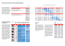
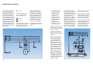
Fig. 3
DESIGNING AN INSTALLATION FOR
HIGH-FREQUENCY ELECTRIC TOOLS.
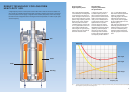
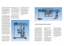
Frequency converter with
synchronic generator
The best solution, technically
speaking, in selecting frequency
converters is the combination
of asynchronic motors with
synchronic generators. The con-
verters are single-wave aggregates
with an asynchronic motor as
drive motor and a brushless
innerpole-generator with built-in
current generator.
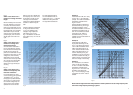
The voltage difference between
idling and operation under full
load is only approx. 3% for small
transformers at cos f 0.6 – 0.9,
for large converters, approx. 4%.
Synchronic converters are not
affected by voltage fluctuations in
the primary rotary current mains
and, in addition, safeguarded
against short circuiting. Assimila-
tion to the rated voltage can be
effected by means of a potentio-
meter. Moreover, the converters
are maintenance-free for 20,000
machine hours.
Secondary frequency is calcu-
lated according to the following
formula:
if
2
=f
1
·p
2
/p
1
f
1
= primary frequency of
rotary current mains
f
2
= secondary frequency for
high-frequency electric
tools
p
1
= pole pair count of the
drive motor
p
2
= pole pair count of the
generator
Frequency converters with a
power output in excess of 4 kVA
should generally not be switched
into the mains direct but con-
nected by means of star delta
switches. When they are switched
in directly, a short-term current
surge occurs. This surge could
overload the lead wires on con-
verters over 4 kVA and trigger
the serial fuse. When a star delta
switch is used, the current surge
is reduced since current flow
over the star switch is reduced
to one third of what it would be
with direct switching.
When a star delta switch is used,
the coil of the drive motor is
switched from the star (switch-on
process) to the delta (operating
position). It is imperative that a
frequency converter that is to be
operated on a 400 V mains line
with a star delta switch is laid
out for 400 V in the delta. If a
converter of this kind is laid out
for only 230 V in the delta, it can
only be switched in to the 400 V
mains directly over the star,
that is to say, without star delta
switching. When laying out a new
installation, it is very important
to take this into consideration.
Parallel operation of
frequency converters
In order to increase the economics
of the entire installation and to
equalize load peaks, frequency
converters can be switched in
parallel. This results in optimal
assimilation to the equipment
being used. When frequency con-
verters are linked to synchronic
generators, no particular prepara-
tions are required to operate
equipment in parallel even when
power output levels differ.
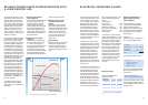
Compensating for reactive
current
Every inductive consumer is
lumbered with a reactive current
that performs no effective work,
but only loads the electrical
wiring. Frequency converters and
high-frequency electric tools are
also inductive consumers.
Compensation for reactive current
on the secondary side of the
converter requires considerable
expenditure since each tool must
be compensated separately.
Depending on the number and
the performance level of the
individual high-frequency electric
tools, a total output factor cos f
of 0.5 to 0.85 is to be reckoned
with. On the primary side of the
frequency converter, the output
factor cos f can be significantly
improved if the magnetizing
current from the drive motor and
generator are compensated.
Switching in correspondingly
rated capacitors makes it possible
to counteract the primary side
reactance output of the converter
almost entirely when idling and to
compensate it under load to such
an extent as to yield an output
factor larger than cos
f = 0.9.
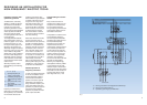
to the tools
a
1
= motor guard switch with magnetic and thermal trip
a
2
= motor guard with thermal trip
b = protective grounding as per VDE 0100