


7170
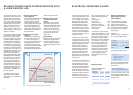
ELECTRICAL SAFETY.
For high-frequency electric tools,
electrical safety is assured by
the protective conductor as per
EN 50144 based on protection
class I. When the secondary coil
of the converter is switched in
the star, the star point or neutral
point is extended outwards. This
neutral point is earthed (earthing
resistance RB
Œ
2 ohms) and
connected to the metal housing
of the electric tools by way of the
protective conductors so that, at
an operating voltage of 265 V, the
dangerous voltage between phase
and earth is only
265 V
1.73
= 153 V
At operating voltages of 135 V
or 72 V, on the other hand, the
dangerous voltage is only
135 V
1.73
= 78 V or
72 V
1.73
= 42 V
The effectiveness of the protective
earthing is assured by using corre-
spondingly robust plug fixtures
of faultless electrical construction
together with suitably resistant
cables. Careful maintenance is
equally important. The electric
tool itself must, in its construction
design, be capable of satisfying
the stringent demands of indus-
trial manufacture. Under normal
circumstances, the description
provided above, e.g. the protec-
tion measure “Earthing" as per
VDE 0100 – 10 N is adhered to.
The possible protective measures
may be classified and subdivided
as follows:
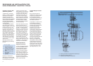
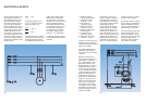
Fig. 4
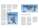
Fig. 5
1.0 protective measures
without switching device
1.1 protective insulation
(VDE 0100 – § 7 N)
1.2 low voltage, 42 V
(VDE 0100 – § 8 N)
1.3 protective separation
(VDE 0100 – § 14 N)
2.0 protective measures with
switching device
2.1 protective earthing
(VDE 0100 – § 9 N)
2.2 reduction to zero voltage
(VDE 0100 – § 10 N)
In cases 2.1 and 2.2, switch-off is
effected by fuses or correspond-
ing thermo-magnetically triggered
station circuit breakers.
The greatest possible degree of
protection is reached by using
fault current (FI) circuit breakers
in addition.
Protective insulation as per 1.1
is not applied to high-frequency
electric tools. Low voltage as
per 1.2 finds application only in
special cases in which, due to
existing regulations, it cannot be
avoided. Because of the high
currents involved, this measure
is very problematic with respect
to cable cross-section, switches,
plugs etc. when applied to the
transmission of large outputs.
Small screw drivers comprise an
exception. In this case, one is
better off using protective sepa-
ration as per 1.3, according to
which every tool must have its
own separator-converter. Protec-
tive separation should be restric-
ted to circumstances in which it
is absolutely necessary.
Here we wish to focus on the
protective measure “reduction to
zero voltage as per 2.2" since it
finds application primarily with
high-frequency electric tools.The
voltage reduction should
continuously prevent excessive
contact potential on installation
parts that do not belong to the
operating circuit (see Fig. 5). It
requires direct earthing of a mid-
point or star point conductor and
is effected by connecting the in-
stallation parts that are to be pro-
tected either to the neutral con-
ductor or to a special protective
conductor that is in turn connec-
ted to the neutral conductor.
The protective measure “reduction
to zero voltage" thus switches off
defective installation parts since
the inline fuse directly before the
defective location is activated.
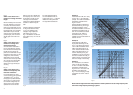
If the fuse is really to be activated,
certain voltage reduction condi-
tions as per VDE 0100 – § 10 N
must be complied with. The most
important voltage reduction
requirement: The cross-section
of the leads from the power