


7372
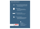
The distribution network must
not have any connection with
the existing 50 Hz supply mains.
For this reason, special CEE
plugged connections as per
DIN 49462/63 and DIN 49465
are prescribed for frequencies
between 100 and 300 Hz. The
housings for the plug, coupling
box and wall socket are all green.
The different shape of these
plugged connections prevents
existing 50 Hz plug units from
being combined with either the
plugs or the coupling boxes.
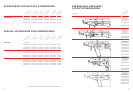
Depending on practical require-
ments, either movable or fixed
leads may be used for the distri-
bution network between the
THE DISTRIBUTION NETWORK.
frequency converter and the
individual high-frequency
electric tools.
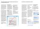
The transmission of high power
levels at low voltage is unecono-
mical in broadly distributed
installations. There will either
be high installation costs due
to the large lead cross-sections
required or else transformers
will be needed to reduce the
higher voltage at the place of
tool operation.
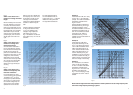
Presupposing a constant level of
power transmission, predefined
voltage drop and equal lead
length, the lead cross-section is
inversely proportional to the
square of the voltage, i.e. half the
voltage will require a lead cross-
section that is four times larger.
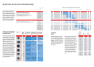
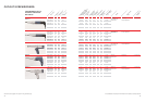
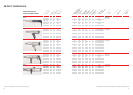
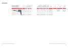
The required distribution network
cross-section can easily be deter-
mined by refering to Figs. 9 to 12.
The admissible voltage drop
of 5 % from ohmic resistance, the
admissible temperature increase
and the voltage drop from induc-
tive resistance are all taken into
account in calculating lead cross-
sections. The illustrations are to
be read as follows:
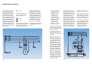
Fig. 6
Fig. 7
generator or converter to the power
consumer must be rated so that the
switch-off current I
A
of the next
upline excess voltage protection unit
according to table I VDE 0100 –
§ 9 N will at least be activated when-
ever a complete short circuit bet-
ween an outer conductor and the
neutral conductor occurs at any
point in the circuitry.
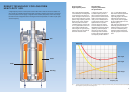
One can also use fault current cir-
cuit breakers in addition, as shown
in Fig. 6 (illustrated, for the sake of
simplicity, for single-phase current).
The FI circuit breaker receives its
impulse from a current transformer
through which all of the lead wires
inclusive neutral con
ductor pass.
The secondary coil of
the current
transformer supplies
the activation
current for the relay
coil of the FI
circuit breaker. The wires surrounded
by the current transformer generate
an alternating magnetic field in the
core of the transformer if all of the
currents do not neutralize each other
in sum total (Fig. 7). During fault-
free condition of the FI circuit
breaker, the current flowing to the
consumer is of exactly the same
magnitude as that flowing back
from it. Thus the two currents neu-
tralize each other. There is no resul-
ting induction onto the secondary
coil of the current transformer, and
the relay coil of the FI circuit brea-
ker remains currentless (Fig. 6).
If there is a fault condition at the
FI circuit breaker, a fault current
flows off through the earth; the
currents in the current transfor-
mer are no longer all mutually
neutralized and induction results.
Voltage is induced on the secon-
dary side of the transformer.
The relay coil in the FI circuit
breaker is activated (Fig. 7). 45 mA
FI circuit breakers are available for
265 V/200 Hz rotary current. FI
circuit breakers for rotary current
at other voltage and frequency
levels must be specially requested
from appropriate manufacturers.
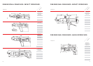
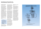
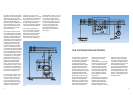
A schematic representation of
an FI circuit breaker is provided
in Fig. 8. In order to accommo-
date the regulations and specific
conditions in other countries,
Bosch offers high-frequency elec-
tric tools for various operating
voltages (265 V, 135 V, 72 V, 42 V at
200 Hz; 200 V, 72 V, 42 V at 300 Hz).
At the lower voltages, however,
only a few high-frequency electric
tools should be used in close pro-
ximity to the associated frequency
converter. This is because the
currents arising at high power
levels and low voltage require
cable cross-sections that would
be too large.