


7574
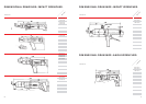
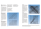
Fig. 9
Fig. 10
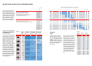
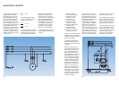
power to be transmitted (AC)
direct current single-phase
alternating current
alter-
nating
current
rubber hose line
securely installed
cross-section (with inductive resistance)
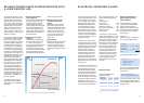
Example a:
Transmission of 4 kW, 72 V rotary
current, cos
f = 0.8, lead length
(simple) 10 m. Cable cross-section
calculated in accordance with
Fig. 9: 2.75 mm
2
.
Cable cross-section calculated in
accordance with Fig. 10: 4.8 mm
2
(selected cross-section: 6 mm
2
)
The cable cross-section of 2.75 mm
2
calculated on the basis of Figs. 9
and 10 is not sufficient; the cable
would get too hot. Testing in
accordance with Fig. 11 is not
necessary since the cross-section is
less than 10 mm
2
.
Example b:
Transmission of 3 kW, 220 V
single-phase alternating current,
cos
f = 0.9, lead length (simple):
100 m. Cable cross-section calcu-
lated in accordance with Fig. 9:
4 mm
2
. Cable cross-section calcu-
lated in accordance with Fig. 10:
0.9 mm
2
. According to Fig. 9, a
crosssection of 4 mm
2
is required.
This value is decisive since Fig. 10
yields a value of only 0.9 mm
2
and
there is no danger of overheating.
Example c:
As in “Example a”, but at 200 Hz
rotary current with lead length
of 100 m. The cable cross-section
calculated in accordance with
Fig. 9 is 27 mm
2
. This value must
be tested in accordance with
Fig. 11. In this example, the larger
cross-section of 50 mm
2
must be
selected.
Bosch Customer Support Services is always available to answer questions on the use of high frequency tools
and the area of high frequency technology in general.
power to be transmitted (AC)
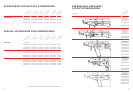
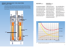
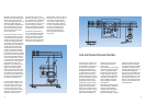
Fig. 8
Fig. 8:
Cable cross-section as a
function of voltage and lead
length
Move horizontally from the left or
the right, depending on the type
of current, with the value of the
power to be transmitted until the
row intersects with the column for
the voltage. Next, move vertically
downwards until you intersect
with the line for the lead length
(simple length), then move hori-
zontally again to the left or the
right.
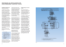
Fig. 9:
Cable cross-section as a
function of voltage and
performance factor
The cross-section calculated in
Fig. 9 is now tested for tempera-
ture rise. Move horizontally from
the left with the value of the
power to be transmitted until you
intersect with the column for the
voltage. Next, move vertically
downwards until you intersect
with the line for the output factor
cos
f; finally, move horizontally
to the right to find the cross-
section for the type of lead you
are using.
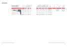
Fig. 10:
Cable cross-section as a
function of frequency and
inductive resistance
If the cross-section for rotary
current resulting from Figs. 9 and
10 exceeds 10 mm
2
, you must
then apply the precise calculated
value to Fig. 10 in order to take
the inductive voltage drop into
account. Next, move vertically
upwards from the horizontal
base line until you intersect with
the frequency curve. Then move
horizontally to the left or right.
The larger of the calculated
values for the cable cross-section
is decisive in determining the
lead.
Inductive resistance is significant
for large cross-sections. These,
in turn, are necessary at low
voltages or high frequencies.
Calculation of the curve in
Fig. 11 was based on an assumed
output factor cos
f of 0.7 for the
consumer.
For single phase alternating
current installations with an
output factor cos
f = 1, inductive
resistance can be ignored even
for large cable cross-sections.