


10
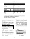
To Regulate Control Set Point
— Turn adjustment nut
clockwise to its bottom stop. In this position, set point is
86 psig. Control set point is then regulated to desired pressure
by turning adjustment nut counterclockwise. Each full turn
decreases set point by approximately 7.2 psi. Approximately
12 turns counterclockwise lowers the control set point to
0 psig. See Table 5.
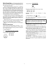
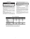
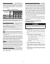
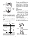
Table 5 — Capacity Control
NOTE: Capacity control valve factory settings for 4-cylinder units
are: 59 psig control set point (cylinder load point), 10 psi differential
(59 psig cylinder unload point). Settings for 6-cylinder units are: left
cylinder bank control set point is 70 psig, differential is 10 psi; right
cylinder bank control set point is 68 psig, differential is 10 psi.
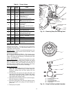
Pressure Differential Adjustment — Turn differential adjust-
ing screw counterclockwise to its back-stop position. In this
position, differential is 6 psi. Pressure differential is set by
turning adjusting screw clockwise. Each full turn increases
pressure differential by approximately 0.8 psi. Approximately
10 turns increases differential to 16 psi.
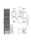
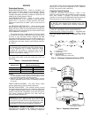
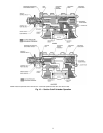
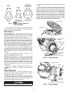
SUCTION CUTOFF UNLOADER OPERATION — The ca-
pacity control valve shown in Fig. 9 is the pressure operated
type. Refer to Fig. 10 and the following description for valve
operation.
Loaded
— When suction pressure rises high enough to over-
come control set point spring, the diaphragm snaps to the left
and relieves pressure against the poppet valve. The drive spring
moves poppet valve to the left and it seats in the closed
position. See Fig. 10.
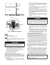
With poppet valve closed, discharge gas is directed into the
unloader-piston chamber and pressure builds up against the
piston. When pressure against unloader piston is high enough
to overcome the unloader valve spring, piston moves valve to
the right, opening suction port. Suction gas can now be drawn
into the cylinders and the bank is running fully loaded.
Unloaded
— As suction pressure drops below set point, con-
trol spring expands, snapping diaphragm to right. This forces
poppet valve open and allows gas from discharge manifold to
vent thru base of control valve to suction side. Loss of full
discharge pressure against unloader piston allows unloader
valve spring to move valve left to closed position. The suction
port is blocked, isolating the cylinder bank from the suction
manifold. The cylinder bank is now unloaded. See Fig. 10.
Service Replacement Compressors
— These compressors are
not equipped with capacity control valves. One side-bank
cylinder head is a bypass unloading type, plugged with a
spring-loaded piston plug assembly. As received, the compres-
sor will run fully loaded.
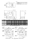
Replacing Suction Cutoff Unloading Heads
— When the
original compressor is equipped with suction cutoff unloading
head(s), the complete cylinder head and control valve assem-
blies must be transferred to the service (replacement) compres-
sor. See Fig. 10 for typical suction cutoff installation. Where
one step of unloading is required, remove the bypass-type
unloader head and valve plate assembly from replacement
compressor (cylinder head next to terminal box). Remove
check valve from the valve plate. Using new gaskets, reinstall
the valve plate assembly and install the suction cutoff head
from the original compressor. Torque the cylinder head
holddown bolts to 90 to 100 lb-ft. For 6-cylinder 2-step suction
cutoff unloading, transfer the second unloading head and
control valve from the original compressor to the replacement
compressor, using the valve plate assembly from the replace-
ment compressor. Use new gaskets.
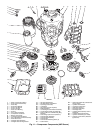
Be sure the new cylinder head gasket is the one shown in
Fig. 11, Item 33, when installing suction cutoff unloader head.
Install parts removed from replacement compressor on
original compressor and seal all openings to prevent
contamination.
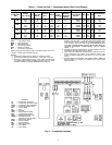
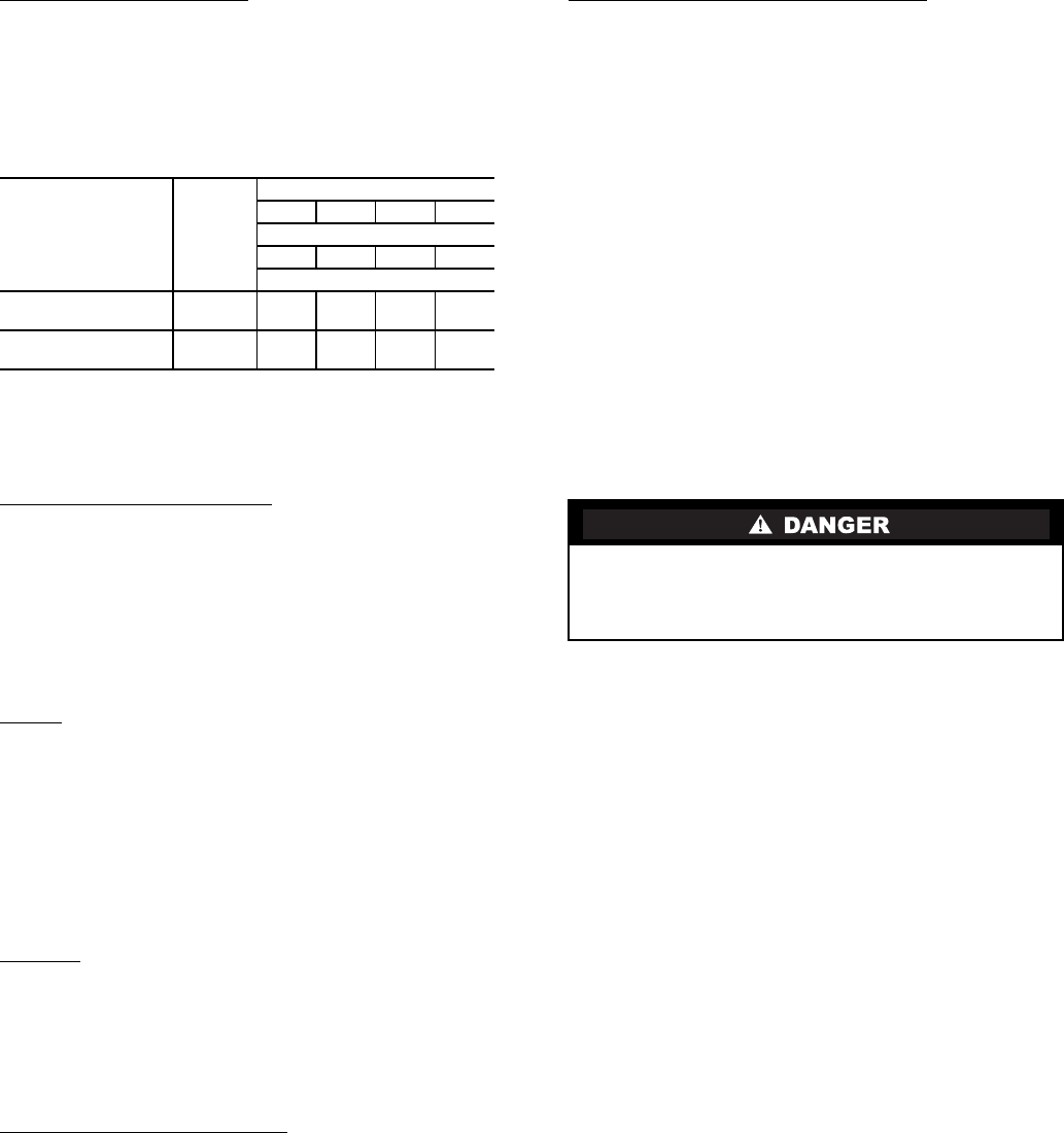
Removing, Inspecting and Replacing
Components (Fig. 11)
SERVICE NOTES
1. All compressors have interchangeable valve plate assem-
blies, unloader valves and oil pump bearing head
assemblies. For replacement items use Carrier Specified
Parts.
2. Before compressor is opened, the refrigerant must be
removed from it by the Pumpdown method:
a. Start compressor, close suction shutoff valve, and
reduce crankcase pressure to 2 psig. (Bypass low
pressurestat with a jumper.)
b. Stop compressor and isolate from system by
closing discharge shutoff valve.
c. Bleed any residual refrigerant. Drain oil if
necessary.
3. After disassembly, clean all parts with solvent. Use
mineral spirits, white gasoline or naphtha.
4. Before assembly, coat all parts with compressor oil and
clean and inspect all gasket surfaces. Replace all gaskets
with new factory-made gaskets. See Table 6 for torque
values.
5. After reassembly, evacuate compressor and open suction
and discharge valves. Restart compressor and adjust
refrigerant charge.
UNIT 06E,07E
NO. OF
CONTR
CYL
% Full Load Capacity
100 67 49 32
% Full Load kW
100 73 57 46
Number of Active Cylinders
ALL 4 CYLINDER
MODELS
24— 2 —
ALL 6 CYLINDER
MODELS
464— 2
Do not remove the compressor terminal box cover until all
electrical power is disconnected and pressure is relieved.
Terminal pins may blow out causing injuries, death, and/or
fire.