


17
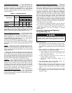
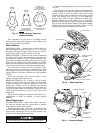
Remove
1. Acorn nut and washer.
2. Back out locking pin and bushing.
Replace
1. Screw in locking pin bushing until it rests on stator core.
2. Wrap a piece of tape around
3
/
8
-in. drill bit, 2
1
/
16
in. from
cutting edge.
3. Ream out bushing (
3
/
8
-in. drill) and drill into stator core
until tape is flush with top of bushing. (Remove drill
chips.) Back off locking pin bushing
1
/
8
of a turn.
4. Tap locking pin into position. (Top of bushing should be
approximately
1
/
16
in. above top of pin.)
5. Peen top of bushing over roll pin.
6. Replace washer and acorn nut.
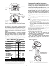
Motor Burnout (Clean-Up Procedure) —
When a
hermetic motor burns out, the stator winding decomposes
forming carbon, water and acid which contaminate refrigerant
systems. Remove these contaminants from system to prevent
repeat motor failures.
1. Close compressor suction and discharge service valves,
and bleed refrigerant from compressor. Save remaining
refrigerant in system.
2. Remove burned motor from compressor, and drain com-
pressor oil. Clean crankcase and motor housing with
solvent. Ensure that all metal particles are wire-brushed
free and removed.
On severe burnouts, disassemble compressor heads and
valve plate assemblies. Clean them in same manner as
crankcase and motor housing.
3. Determine cause of burnout and remedy. Check control
box for welded starter contacts, welded overload contacts
or burned out heater elements. Check terminal plate for
burned or damaged terminals, insulation, and shorted or
grounded terminals.
4. Reassemble compressor with new stator and rotor. Install
new liquid line filter drier, and place new oil charge in
crankcase.
5. Evacuate and dehydrate compressor.
6. Place compressor in operation. After 2 to 4 hours of
operation, check compressor oil for discoloration and/or
acidity. If oil shows signs of contamination, replace oil
charge, filter driers, and clean suction strainer with
solvent.
7. Check oil daily for discoloration and acidity. If oil stays
clean and acid-free, the system is clean. If oil shows signs
of contamination, change oil, filter drier, and clean
suction strainer. If filter drier or suction strainer is dirty or
discolored, repeat this step until system is clean.
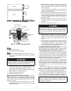
Condenser Maintenance (07E Units) —
To inspect
and clean condenser, drain water and remove condenser heads.
To drain condenser, shut off water supply and disconnect inlet
and outlet piping. Remove drain plugs and vent plug.
With condenser heads removed, inspect tubes for refrigerant
leaks. (Refer to Carrier Refrigerant Service Techniques Manual.)
Clean condenser tubes with nylon brush (available from
Carrier Service Department). Flush water through tubes while
cleaning. If hard scale has formed, clean tubes chemically. Do
not use brushes that will scrape or scratch tubes.
Because the condenser water circuit is usually an open
system, the condenser tubes may be subject to contamination
by foreign matter. Local water conditions may cause excessive
fouling or pitting of tubes. Condenser tubes, therefore, should
be cleaned at least once a year or more often if the water is
contaminated.
Proper water treatment can minimize tube fouling and
pitting. If such conditions are anticipated, water treatment
analysis is recommended. Refer to the Carrier System Design
Manual, Part 5, for general water conditioning information.
If hard scale has formed, clean the tubes chemically. Con-
sult an experienced and reliable water treatment firm in your
area for treatment recommendations. Clean the condenser by
gravity or by forced circulation as shown in Fig. 24 and 25.
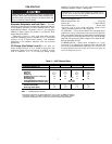
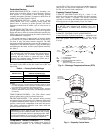
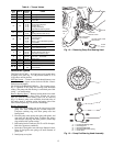
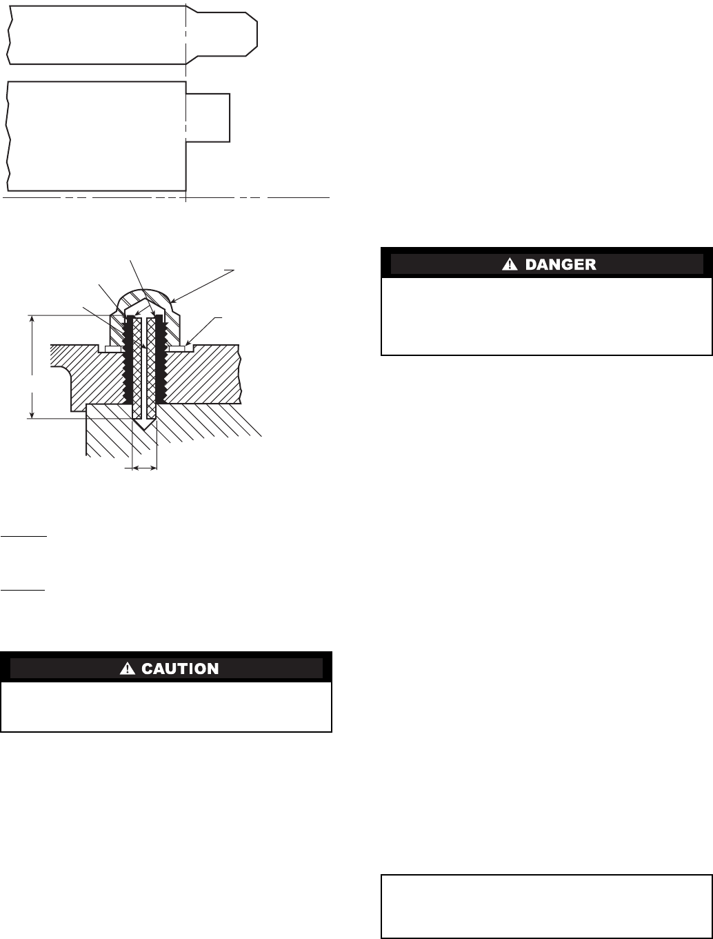
Before drilling, be sure stator vent holes do not line up with
locking pin hole. Vent holes are drilled horizontally
through stator, and can be seen from end bell side.
Do not attempt start-up with terminal cover removed.
Bodily injury or death may result from explosion and/or
fire if power is supplied to compressor with the terminal
cover removed or unsecured. See warning label on termi-
nal cover.
IMPORTANT: If the ambient temperature is below 32 F
during a shutdown period, protect the condenser from
freezing by draining the water from the system or by add-
ing antifreeze to the water.
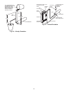
STATOR
END
TURN
ROTOR
END
RING
ROTOR CENTER LINE
PEENED ENDS
ACORN NUT
BUSHING
LOCKING PIN
WASHER
COMPRESSOR
CASTING
STATOR CORE
3/8"
2 1/16"
Fig. 22 — Motor Alignment
Fig. 23 — Stator Locking Assembly