


9
SERVICE
Protection Devices
HIGH-PRESSURE SWITCH — Check by throttling con-
denser water or blocking airflow on air-cooled units, allowing
head pressure to rise gradually. Check discharge pressure
constantly throughout procedure. Compressor should shut off
within 10 psi of values shown in Table 4.
LOW-PRESSURE SWITCH — Check by slowly closing
suction shutoff valve or by completely closing liquid line
shutoff valve. A decrease of suction pressure will follow.
Compressor should shut off within 4 psi of values shown in
Table 4.
OIL PRESSURE SWITCH (OPS) — The oil pressure switch
protects against damage from loss of oil or loss of oil pressure
during unit start-up. If the oil pressure differential sensed by the
OPS is 6 psig or less on unit start-up, the switch remains closed
and the OPS heater is energized.
The switch time delay is approximately 45 seconds. If after
45 seconds the oil pressure differential sensed by the OPS is
less than 11 psig, the heater remains energized. The OPS
temperature actuated switch then opens and the compressor is
deenergized. If the differential reaches 11 psig, the OPS opens
and deenergizes the heater and the system operates normally.
See Table 4.
To restart the unit, push the OPS reset button and then push
the control circuit switch on the unit control box to OFF and
then to ON.
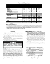
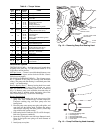
Table 4 — Factory Switch Settings
NOTES:
1. Values for the high- and low-pressure switches based on R-22.
For other refrigerants, reset to pressure corresponding to satura-
tion temperatures indicated by the listed pressures.
2. Values for oil pressure are above operating suction pressure
(pressure differential between suction and discharge pressures
of oil pump).
TIME GUARD® CONTROL — The Time Guard control
protects against short cycling. See Start Compressor.
CRANKCASE HEATER — The crankcase heater prevents
absorption of liquid refrigerant by oil in crankcase during brief
or extended shutdown periods. Source of 115-volt power is the
auxiliary control power, independent of the main unit power.
This assures compressor protection even when main unit
power disconnect switch is off.
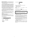
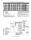
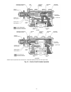
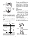
Compressor Thermal Protection —
A discharge
temperature sensor, installed in one cylinder head, detects an
overtemperature condition. If the discharge temperature
exceeds 295 ± 5 F, the sensor contacts open and the compressor
shuts down. The sensor reset temperature is 235 F minimum.
See Fig. 8 for control circuit connections.
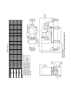
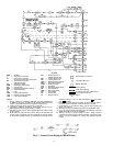
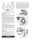
Capacity Control System
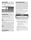
CAPACITY CONTROL VALVE (Fig. 9) — Valve is con-
trolled by suction pressure and actuated by discharge pressure.
Each valve controls 2 cylinders. On start-up, controlled
cylinders do not load up until differential between suction and
discharge pressures is approximately 25 psi. See Table 5.
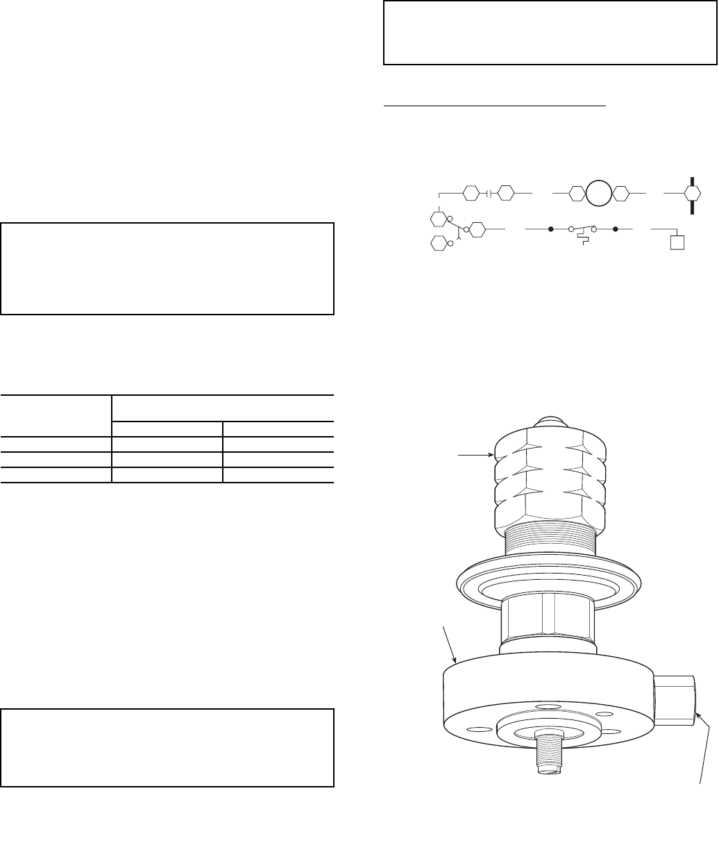
CAPACITY CONTROL VALVE ADJUSTMENTS
Control Set Point (Cylinder Load Point)
— Adjustable from
0 to 86 psig. Pressure differential between cylinder load-up
point and cylinder unload point is adjustable from 6 psi
to 16 psi.
IMPORTANT: If the oil pressure switch causes unit lock-
out, determine and correct the cause of the lockout (such as
loss of compressor oil or flooded compressor) before
restarting the unit. Failure to correct the cause of OPS
lockout may constitute abuse. Equipment failure due to
abuse is not covered by warranty.
SWITCH TYPE
PRESSURE CHANGE AFFECTING
SWITCH POSITION (psig)
Closed Open
High Pressure
210 (±10) 290 (±10)
Low Pressure
70 (±4) 60 (±4)
Oil Pressure
611
IMPORTANT: Never open any switch or disconnect that
will deenergize the crankcase heater unless unit is being
serviced or is to be shut down for a prolonged period. After
a prolonged shutdown or a service job, energize the crank-
case heater for 24 hours before starting the compressor.
IMPORTANT: Do not use automatic pumpdown control
on 06E,07E units equipped with unloader valves. Use
single pumpout or solenoid drop (minimum protection)
control.
CONTROL
SET POINT
ADJUSTMENT
NUT
VALVE BODY
SEALING CAP
(COVERS PRESSURE DIFFERENTIAL
ADJUSTMENT SCREW)
Fig. 9 — Capacity Control Valve
TIMER
CONTACTS
BLU
ORN
B2
B1
CR
46
RED
C1
C2
C2
DTS
BLU
YEL
TB2
6
C2
C1
B
LEGEND
Fig. 8 — Discharge Temperature Sensor (DTS)
C—
Compressor Contactor
CR —
Control Relay
DTS —
Discharge Temperature Sensor
TB —
Terminal Block
•
Splice (in compressor junction box)