


8
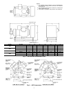
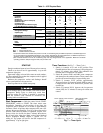
Table 3 — 07E Physical Data
LEGEND
*Compressor listed is the standard compressor for R-22, air conditioning duty. An 06ER compressor is standard equipment
for low temperature (R-507/404A) applications. For medium temperature (R-134a) applications, an 06EM compressor is
standard. Factory substitutions may be made. Contact Carrier Sales Representative.
†The condenser listed is for R-22, air conditioning duty and may change based on the application. Maximum condenser
operating pressure: 350 psi refrigerant side, 150 psi water side.
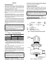
START-UP
Energize crankcase heater at least 24 hours prior to start-up.
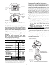
Check to see that oil level is approximately
1
/
3
up on the
compressor sight glass.
Open water supply valve and allow water to reach condens-
er. (Turn condenser fan on when the compressor unit is applied
with air-cooled condenser.)
Backseat the compressor suction and discharge shutoff
valves; open liquid line valve at receiver.
Start evaporator fan or chilled water pump.
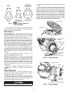
Start Compressor —
Push the control circuit START-
STOP-RESET switch to START. The timer motor starts
immediately. Depending on the position of the timer, the
compressor start is delayed for 12 seconds to approximately
8 minutes. Check oil pressure after compressor has run a few
minutes; the pressure should be 12 to 18 psi above the suction
pressure. After about 20 minutes of operation, stop the com-
pressor. Allow it to be idle for about 5 minutes, then observe
the oil level in the sight glass. Refer to the Carrier Standard
Service Techniques Manual, Chapter 1, Section 1-11, for
adding oil. The proper oil level for the 06E compressor is
approximately
1
/
3
up on sight glass.
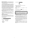
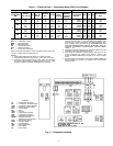
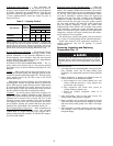
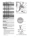
Timer Functions
(See Fig. 7 — Timer Cycle.)
1. Switch A (contacts A-A1 and A-A2) provides Time
Guard® function. Start of compressor is delayed approxi-
mately 5.5 minutes after shutoff. The minimum time
between starts of compressor is 8 minutes.
2. Switch B (contacts B-B1 and B-B2) starts compressor
and deenergizes the crankcase heater. These contacts also
provide one-second time delay for part-winding start.
3. Switch E (contacts E-E1) provides approximately
40-second bypass of oil pressure switch (OPS) at start-up.
Compressor will shut off if sufficient oil pressure does
not build up.
4. Switch D (contacts D-D1) bypasses the low-pressure
switch (LPS) for 2.5 minutes at start-up for winter start
control.
UNIT 07E A022 B027 B033 D044
OPERATING WEIGHT (lb)
1090 1200 1250 1410
REFRIGERANT
R-134a, R-22, R-507/404A
COMPRESSOR — 06E*
A250 A265 A275 A299
Cylinders
4666
Bore (in.)
2
11
/
16
2
11
/
16
2
11
/
16
2
11
/
16
Stroke (in.)
2
3
/
16
22
3
/
16
2
7
/
8
Displacement (cfm at 1750 rpm)
50 68 75 99
Maximum Rpm
1750
Oil Charge (pt)
14 19 19 19
High Side Maximum Pressure (psi)
450
Low Side Maximum Pressure (psi)
245
CONDENSER (Shell and Tube)† Part Number
P701-0840AX P701-0850AX P701-0850AX P701-1065AX
Refrigerant Storage
Capacity (lb)
R-134a
71.3 85.90 85.90 112.70
15.4 18.67 18.67 23.77
R-22
70.4 84.80 84.80 111.20
Min Refrigerant Operating
Charge (lb)
15.1 18.30 18.30 23.30
R-507/404A
61.1 73.60 73.60 96.50
15.1 18.30 18.30 23.30
REFRIGERANT CONNECTION (in. ODF)
Inlet
2
1
/
8
2
1
/
8
2
1
/
8
2
5
/
8
Outlet
1
3
/
8
1
3
/
8
1
3
/
8
1
5
/
8
WATER CONNECTION (in. FPT)
Inlet/Outlet
2
1
/
2
2
1
/
2
2
1
/
2
3
FPT —
Female Pipe Thread
ODF —
Outside Diameter, Female
Do not attempt start-up with terminal cover removed from
compressor. Bodily injury or death may result from
explosion and/or fire if power is supplied to compressor
with the terminal cover removed or unsecured. See
warning label on terminal cover.
Fig. 7 — Timer Cycle