


5
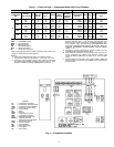
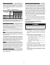
Table 1 — Electrical Data — Compressor Motor With Circuit Breaker
LEGEND
*Refer to physical data table to match compressor with correct com-
pressor or water-cooled condensing unit.
NOTES:
1. Compressor MTA and RLA values are maximum figures.
2. LRA values for PW second winding =
1
/
2
the LRA – XL value.
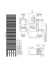
3. 3-Pole XL circuit breakers shown, other 3-Pole XL alternates
and 6-Pole PW breakers available. Terminal lugs for circuit
breakers available in package 06EA660152 (not shown).
4. Recommended RLA value shown is determined by: circuit
breaker must trip value
÷
1.40. Use this recommended (and
minimum) RLA value to determine nameplate stamping, mini-
mum contactor sizing, and wire sizing. RECOMMENDED RLA
FOR 06E COMPRESSORS EQUALS: MUST-TRIP (MTA) OF
CARLYLE APPROVED OVERCURRENT DEVICE BEING
USED
÷
1.40
5. Compressor operating amps at any specific condition can only
be determined from a performance curve.
6. Ohm values for resistance are approximate and shown for ref-
erence purposes only. Motors from different vendors and
motors of different efficiencies can differ up to 15% from data
shown.
7. Electrical data for compressor part numbers 06ER, 06EM and
50 Hz models (not shown) are available from Carrier Sales
Representative.
COMPRESSOR MOTOR DATA CIRCUIT BREAKER
Compressor
Part Number
06E*
Voltage
(3 Ph - 60 Hz)
Hp
Maximum
Must Trip
Amps
Maximum
RLA
LRA-XL
LRA-PW
(first
winding)
Motor
Winding
Resistance
(Ohms)
Recommended
Circuit Breaker
Part No.
MHA MTA LRA
Recommended
RLA
A
250
208/230
20
108 87 345 207 0.32 HH83XB336 91 104 350 74.3
575 45 36 120 72 2.2 XA461 33 38 124 27.1
460 54 44 173 104 1.3 XA424 42 49 175 35.0
265
208/230
25
140 112 446 268 0.27 HH83XC509 110 127 420 90.7
575 57 46 164 98 1.6 XA469 46 53 164 37.9
460 70 56 223 134 1.1 XA426 55 643 210 45.7
275
208/230
30
168 135 506 304 0.22 HH83XC539 142 163 507 116.4
575 65 52 176 106 1.3 XA430 50 58 168 41.4
460 84 68 253 152 0.9 XA425 63 73 210 52.1
299
208/230
40
236 189 690 414 0.15 HH83XC537 187 215 636 153.6
575 94 75 276 165 1.0 XA551 74 85 236 60.7
460 118 95 345 207 0.58 XA550 92 106 295 75.7
LRA —
Locked Rotor Amps
MHA —
Must Hold Amps
MTA —
Must-Trip Amps
PW —
Part-Winding (Start)
RLA —
Rated Load Amps
XL —
Across-the-Line (Start)
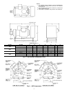
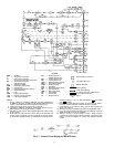
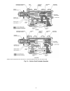
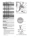
Fig. 5 — Component Location
LEGEND
C1 —
Compressor Contactor
C2 —
Compressor Contactor (PW)
CCB —
Compressor Circuit Breaker
CHR —
Crankcase Heater Relay
CR —
Control Relay
FU —
Fuse
GND —
Ground
HPS —
High-Pressure Switch
LPS —
Low-Pressure Switch
NEC —
National Electrical Code
NEMA —
National Electrical
Manufacturer’s Association
OPS —
Oil Pressure Switch
POR —
Pumpout Relay
TB —
Terminal Block
TDR —
Time Delay Relay
TM —
Timer Motor
TR —
Timer Relay