


3
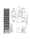
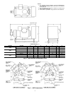
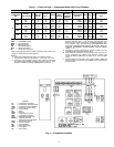
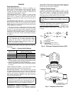
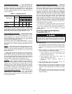
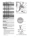
Fig. 2 — 07E Water-Cooled Condensing Units
DIMENSIONS (in.)
UNIT 07E VOLTS A B C D E F G H I
A022
208/230 66 49
3
/
4
2
3
/
4
34 27
1
/
2
121 5
9
/
16
9
5
/
16
460, 575 66 43
3
/
4
2
3
/
4
34 26 1 21 5
9
/
16
9
5
/
16
B027
208/230 78 49
3
/
4
2
3
/
4
34 27
1
/
2
121 5
9
/
16
9
5
/
16
460, 575 78 43
3
/
4
2
3
/
4
34 26 1 21 5
9
/
16
9
5
/
16
B033
208/230 78 49
3
/
4
2
3
/
4
34 27
1
/
2
121 5
9
/
16
9
5
/
16
460, 575 78 43
3
/
4
2
3
/
4
34 26 1 21 5
9
/
16
9
5
/
16
D044
208/230 69
1
/
2
49
3
/
4
2
3
/
4
34 27
1
/
2
121 4
1
/
8
8
5
/
8
460, 575 69
1
/
2
49
3
/
4
2
3
/
4
34 27
1
/
2
121 4
1
/
8
8
5
/
8
NOTES:
1. For standard service practices, such as trouble-
shooting and refrigerant charging, allow a minimum
2
′
-6
″
clearance around the unit.
2. Recommended service space for condenser tube
removal is one condenser length at either end.
3. For compressor removal, allow a minimum 3
′
wide
access aisle to and from the unit.
4. Local codes or jurisdiction may prevail for unit
clearances.