


14
Cylinder Heads (See Fig. 11) —
Disassemble cyl-
inder heads by removing cap screws, and prying up on side
lifting tabs to break heads loose from valve plates. Do not hit
cylinder heads to break loose.
Check heads for warping, cracks and damage to gasket
surfaces. When replacing cylinder head, torque cap screws
90 to 100 lb-ft (prevents high to low side leak in center portion
of cylinder head gasket).
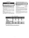
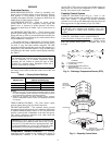
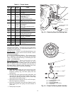
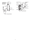
Pressure Relief Valve —
This internal safety device is
located in center cylinder bank (6-cylinder compressors,
Fig. 14) or under discharge service valve (4-cylinder compres-
sors). The valve relieves refrigerant pressure from high to low
side at 400 psi pressure differential. Check valve for evidence
of leaking. Change if defective or if valve has ever opened due
to excessive pressure. Use a standard socket-type screwdriver
to remove and replace valve.
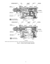
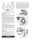
Suction and Discharge Valve Plate Assembly
TEST — Leak test for leaking discharge valves by pumping
compressor down and observing suction and discharge pres-
sure equalization. If a discharge valve is leaking, pressures will
equalize rapidly. Maximum allowable discharge pressure drop
is 3 psi per minute.
If there is an indicated loss of capacity and discharge valves
check properly, remove suction and discharge valve plate
assembly and inspect suction valves.
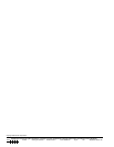
DISASSEMBLE — Remove cylinder head.
1. Remove discharge valve assembly: cap screws, valve
stops, valve stop supports and valves.
2. Pry up on side lifting tab to remove valve plate and
expose suction valves (Fig. 15). Remove suction valves
and backers from dowel pins.
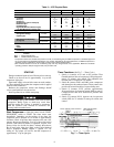
Inspect valves and valve seats for wear and damage (see
Wear Limits, Table 7). Replace valves if cracked or worn. If
valve seats are worn, replace complete valve plate assembly.
REASSEMBLE — Do not interchange valves. Install brack-
ets and suction valves on dowel pins (backer is under the valve;
see Fig. 15). Place valve plate on cylinder deck and reinstall
discharge valve assembly. Retorque discharge valve stop cap
screws to 16 lb-ft. Replace cylinder head. (Be sure tab on
cylinder head gasket is lined up with tabs on cylinder head and
valve plate.)
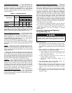
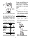
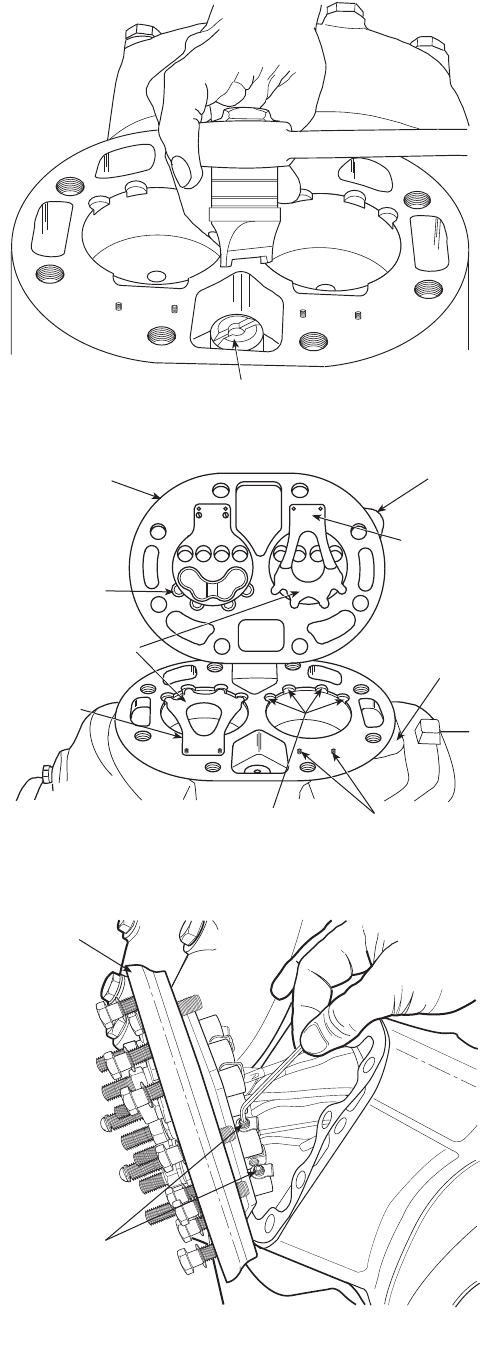
Terminal Plate Assembly —
If there is a refrigerant
leak between the terminal plate and the compressor, remove
plate assembly and replace gasket.
If any terminal is shorted to the terminal plate, replace
complete plate assembly, using a new gasket.
Do not remove the terminal plate assembly except for the
above conditions.
REMOVAL — Remove junction box from terminal plate, and
remove cap screws holding terminal plate to compressor. Mark
all motor leads so they can be reassembled correctly to terminal
plate. Loosen Allen head screws holding motor leads to termi-
nal plate (Fig. 16). Remove terminal plate.
REINSTALL — In reverse sequence, reinstall making sure
motor leads are correct. Torque terminal plate cap screws per
Table 6.
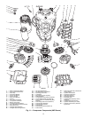
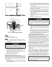
Compressor Running Gear Removal
CONNECTING ROD/PISTON ASSEMBLY — Remove cyl-
inder heads, valve plate assemblies, crankcase bottom cover
plate, oil filter screen, and connecting rod caps (Fig. 17). Label
caps and rods so they may be reinstalled in same place on
crankshaft. Push connecting rod and piston assemblies up
through cylinder deck. Disassemble connecting rods from
pistons by removing retaining rings and piston pins. Remove
oil and compression rings from piston.
Keep each connecting rod and piston assembly together for
proper reassembly. Check all parts and crankpins for wear
(refer to Table 7 for wear limits).
VALVE PLATE
SECTION VALVE
SEATS
(VALVE PLATE)
SUCTION VALVES
(BACKER IS
UNDER THE
VALVE)
TAB
SUCTION
VALVE
BACKER
SUCTION VALVE STOPS
(CYLINDER DECK)
DOWEL
PINS
TAB
PRESSURE RELIEF VALVE
TERMINAL
PLATE
ASSEMBLY
ALLEN HEAD
SCREWS (1/4”)
Fig. 14 — Pressure Relief Valve Removal
Fig. 15 — Valve Plate Removed
Fig. 16 — Removing Terminal Plate Assembly