


16
Turn crankshaft to be sure there is no binding between
bearing surfaces and journals. Replace oil screen, bottom cover
plate, valve plates and cylinder heads.
Motor Removal
MOTOR END BELL — Remove motor end bell carefully to
prevent damage to the stator. Use three
7
/
16
- 14- x 5-in. studs
for guides and support. Inspect suction strainer in end bell.
Clean it with solvent or replace if broken or corroded.
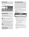
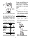
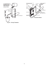
REMOVE ROTOR — Bend rotor lock washer tab backward
and remove rotor lock bolt. If crankshaft turns, preventing lock
bolt from being loosened, remove a cylinder head and valve
plate and place a rubber plug (06R suction plug) on top of one
piston (Fig. 20). Replace valve plate assembly and cylinder
head (only 2 bolts required to hold cylinder head in place). Pro-
ceed to remove rotor lock bolt, lock washer and plate washer.
Use a jackscrew to remove rotor (Fig. 20). Insert a brass
plug into rotor hole to protect end of crankshaft from jack-
screw. Support rotor while it is being removed to prevent stator
damage. Remove ring spacer between rotor and crankshaft
(if used).
Clean rotor thoroughly with solvent. If stator is to be
replaced, a matching rotor must be used.
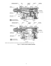
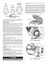
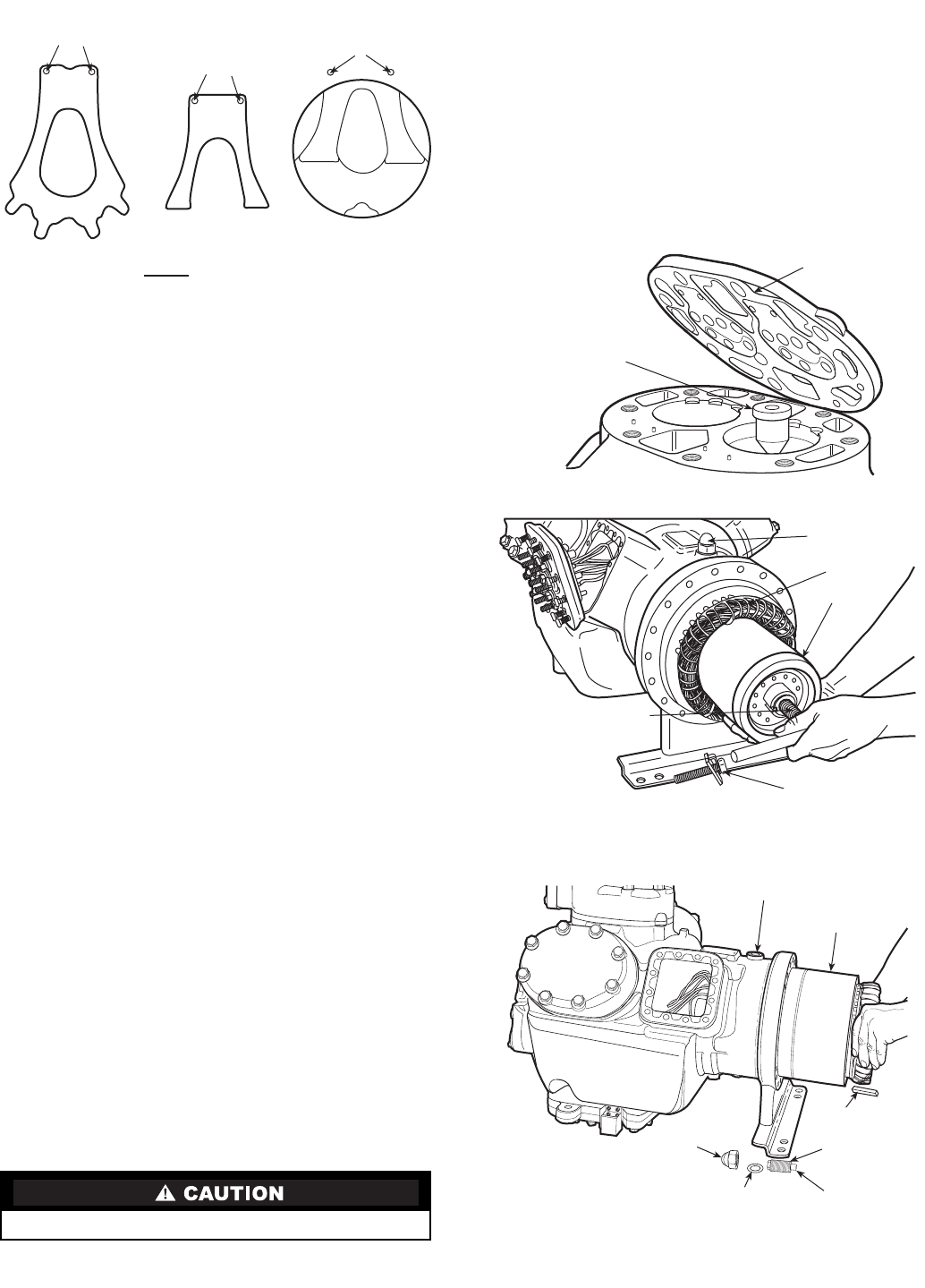
REMOVE STATOR (Fig. 21) — Stator is a slip fit in motor
housing. It is held in place by both an axial key and a locking
assembly consisting of an acorn nut, locking pin, motor lock
bushing and a washer (see Fig. 21). Remove acorn nut and
washer. Back out locking pin and bushing and slide stator out.
Axial key positions stator and crankcase. If necessary, heat
crankcase motor housing (not over 20 to 30 F above stator
temperature).
Check stator for damage to windings and lead wires. Use a
megohmmeter to check for grounds or shorts between
windings.
Motor Replacement
STATOR AND ROTOR — Install stator halfway into hous-
ing. Insert the terminal leads first, guiding them to terminal
plate opening as stator is being inserted.
Replace ring spacer (Fig. 11, item 21) on crankshaft. Ease
rotor onto shaft until it begins to feel snug. Insert rotor key, and
push rotor the remainder of the way on shaft. Replace rotor
lock bolt with lockwasher and plate washer.
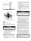
Push stator into housing until it lines up correctly with rotor
(Fig. 22).
Line up keyways in stator and crankcase and replace stator
locking assembly, then drive key into keyway and stake over
keyway in stator to secure key. When a new motor is being
installed, the stator must be drilled and a new locking pin and
motor lock bushing used (see Fig. 23 and instructions).
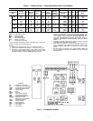
Connect stator leads to proper terminals on terminal plate.
Refasten terminal plate and junction box to compressor.
Replace motor end bell using studs for support. Remove rubber
plug (if used) from piston head. Replace valve plate assembly,
cylinder head, and terminal plate assembly. Torque 12 bolts
holding terminal plate to crankcase at 30 to 40 lb-ft.
Do not push stator in completely until rotor is in place.
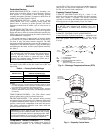
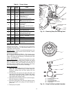
DOWEL
HOLES
DOWEL
HOLES
DOWELS IN
CYLINDER DECK
FOR SUCTION
VALVE AND BACKER
SUCTION
VALVE
BACKER
PLACE AGAINST
CYLINDER DECK,
UNDER SUCTION VALVE
TOP VIEW OF PISTON
IN CYLINDER
Fig. 19 — Piston, Suction Valve and
Backer Positions
VALVE PLATE
RUBBER PLUG
STATOR LOCKING
ASSEMBLY
STATOR
ROTOR
ROTOR LOCK BOLT
JACKSCREW
LOCKING PIN BOSS
STATOR
KEY
ACORN
NUT
WASHER
LOCKING PIN
MOTOR LOCK
BUSHING
Fig. 20 — Removing Rotor
Fig. 21 — Removing Stator