


13
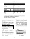
Table 6 — Torque Values
Lubrication System
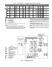
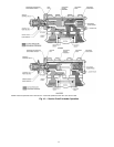
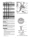
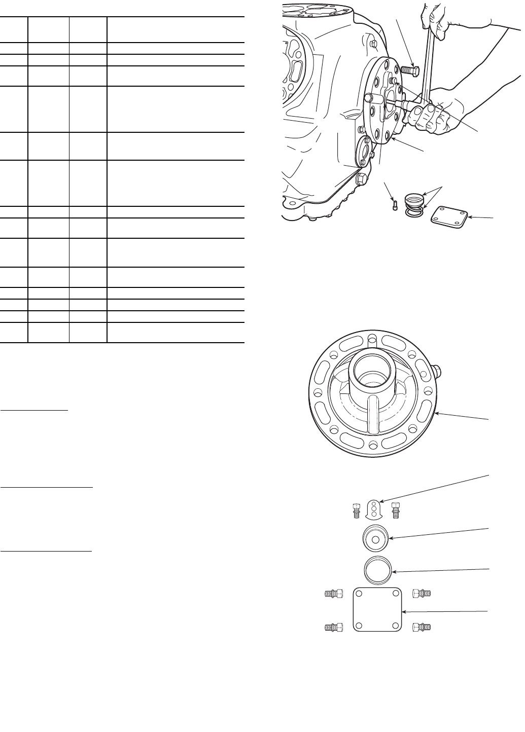
TESTING OIL PUMP — An oil pressure tap is located above
oil pump cover plate (Fig. 12). Oil pressure should be 12 to
18 psi above suction pressure.
Oil Filter Screen
— Screen is accessible through bottom cover
plate. Remove and inspect strainer for holes and dirt. Clean it
with solvent and replace.
OIL PUMP AND BEARING HEAD — The oil pump assem-
bly is contained in the pump end bearing head aluminum
casting. (The pump end main bearing is a machined part of this
casing — no insert bearing.)
Remove Bearing Head
— Remove bearing head from crank-
case and disassemble oil pump. Drive segment cap screws
must be removed before bearing head can be removed
(Fig. 12). Remove pump vane assemblies from both sides of
the bearing head by pushing against the bearing side of the
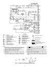
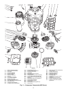
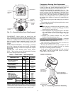
rotor. Check all parts (Fig. 13) for wear and damage.
Replace Bearing Head
1. Install the rotor retaining ring in the ring groove of the
pump rotor with chamfered edge toward compressor.
Compress retaining ring, and insert pump rotor into
bearing head.
2. Place the pump vanes, pump vane spring with guides, and
snap rings into the bearing head. Compress the springs
and force the snap rings into their grooves. (Insert snap
rings with flat side against casting.)
3. Bolt bearing head to crankcase (use 55 to 65 lb-ft torque).
Bolt drive segment to crankshaft.
4. Insert the oil feed guide vane with large diameter inward.
Place oil feed guide vane spring over small diameter of
guide vane.
5. Install pump cover plate.
SIZE
DIAM
(in.)
THREADS
PER IN.
TORQUE
RANGE
(lb-ft)
USAGE
1
/
16
27 (pipe) 8-12 Pipe Plug — Crankshaft
1
/
4
18 (pipe) 20-25 Pipe Plug — Crankcase
1
/
4
20
8-10 Conn. Rod Cap Screw
8-12 Junction Box
1
/
4
28
3-5 Sight Glass
14-18 Oil Pump Drive Segment
14-18 Unloader Valve
14-18 Discharge Valve Stop
12-15 Head Gasket Positioning Screw
5
/
16
18 (pipe)
15-24
Cover Plate — Pump End Bearing
Head
15-24 Discharge Service Valve (4 cyl)
3
/
8
16
30-40 Bottom Plate — Crankcase
30-40 Compressor Foot
30-40 Terminal Plate
25-30 Oil Plug — Pump End Bearing Head
2-4 Terminal Bolts
3
/
8
18 (pipe) 30-40 Pipe Plug — Junction Box
7
/
16
14
55-65 Motor End Cover
55-65 Pump End Bearing Head
1
/
2
13
90-100 Cylinder Head
90-120 Discharge Service Valve (6 cyl)
90-120 Suction Service Valve (4 cyl)
5
/
8
11
90-120 Suction Service Valve (6 cyl)
90-120 Rotor Lock — Crankshaft
5
/
8
18 60-75 Oil Drain Plug
3
/
4
16 105 Stator Lock
No. 6
32 1-2 Check Valve Body — Crankcase
No. 10
32
4-6 Oil Pump Drive Segment
4-6 Terminal Screw
1
2
3
4
5
REMOVE 8 CAP
SCREWS
DRIVE SEGMENT
CAP SCREWS
OIL FEED GUIDE VANE
AND SPRING
OIL
PRESSURE
TAP
PUMP END
BEARING HEAD
COVER
PLATE
Fig. 12 — Removing Pump End Bearing Head
LEGEND
Fig. 13 — Pump End Bearing Head Assembly
1—
Pump End Bearing Head
2—
Drive Segment
3—
Oil Feed Guide Vane
4—
Oil Feed Guide Vane Spring
5—
Cover Plate