


12
34
35
36
37
38
40
41
29
30
28 27
13
11
12
41
24
25
26
789
31
32
33
1
2
5
6
3
4
14 15 16 17
18
19 10
20
21 23 22
31
31
32
33
38
32
39
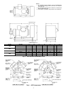
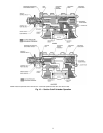
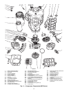
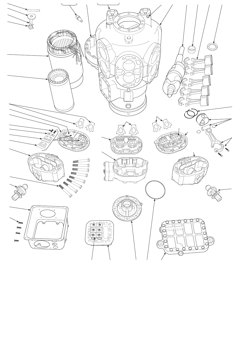
LEGEND
1—
Stator (Compressor Motor)
2—
Rotor (Compressor Motor)
3—
Motor Key
4—
Rotor Plate Washer
5—
Rotor Lock Washer
6—
Rotor Lock Bolt
7—
Motor Lock Bushing
8—
Roll Pin
9—
Acorn Nut and Gasket
10 —
Compressor Crankcase
11 —
Bottom Cover Plate
12 —
Crankcase Oil Filter Screen
13 —
Pump End Bearing Head Assembly
14 —
Motor End Cover
15 —
Oil Sight Glass Assembly
16 —
Oil Sight Glass O-Ring Gasket
17 —
Oil Sight Glass Screw
18 —
Oil Sight Glass Lock Washer
19 —
Pipe Plug (Hex Head)
20 —
Crankshaft
21 —
Ring Spacer (when required)
22 —
Bearing Washer
23 —
Connecting Rod and Piston Assembly
24 —
Connecting Rod and Cap Assembly
25 —
Piston, Piston Pin and Retaining Ring
Package
26 —
Piston Rings (Oil and Compression)
27 —
Terminal Plate Assembly
28 —
Terminal Bolt Assembly
29 —
Terminal Box
30 —
Terminal Box Mounting Screw (4)
31 —
Suction Valve
32 —
Valve Plate Assembly (includes dis-
charge valves)
33 —
Cylinder Head Gasket
34 —
Cap Screw, Valve Stop
35 —
Valve Stop Support
36 —
Discharge Valve Stop
37 —
Discharge Valve
38 —
Cylinder Head (Capacity control,
side bank)
39 —
Cylinder Head (Center bank)
40 —
Cylinder Head Bolt (8 per head)
41 —
Capacity Control Valve (Pressure
type shown)
Fig. 11 — Compressor Components (06E Shown)