


For technical questions, please call 1-800-444-3353;
Troubleshooting section at end of manual.
Page 13SKU 95424, 95629
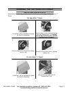
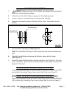
INSTALLING A WIRE SPOOL
Assembling the Wire Spool depends on whether you are using a 7” Spool or an 11”
Spool.
For use with a 7” Spool:
MIG&ARC 250 AMP - SKU 95424
MIG DUAL 250 AMP – SKU
For technical questions, please call 1-800-444-3353;
Troubleshooting section at end of manual.
Page 14
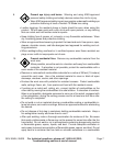
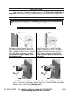
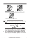
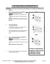
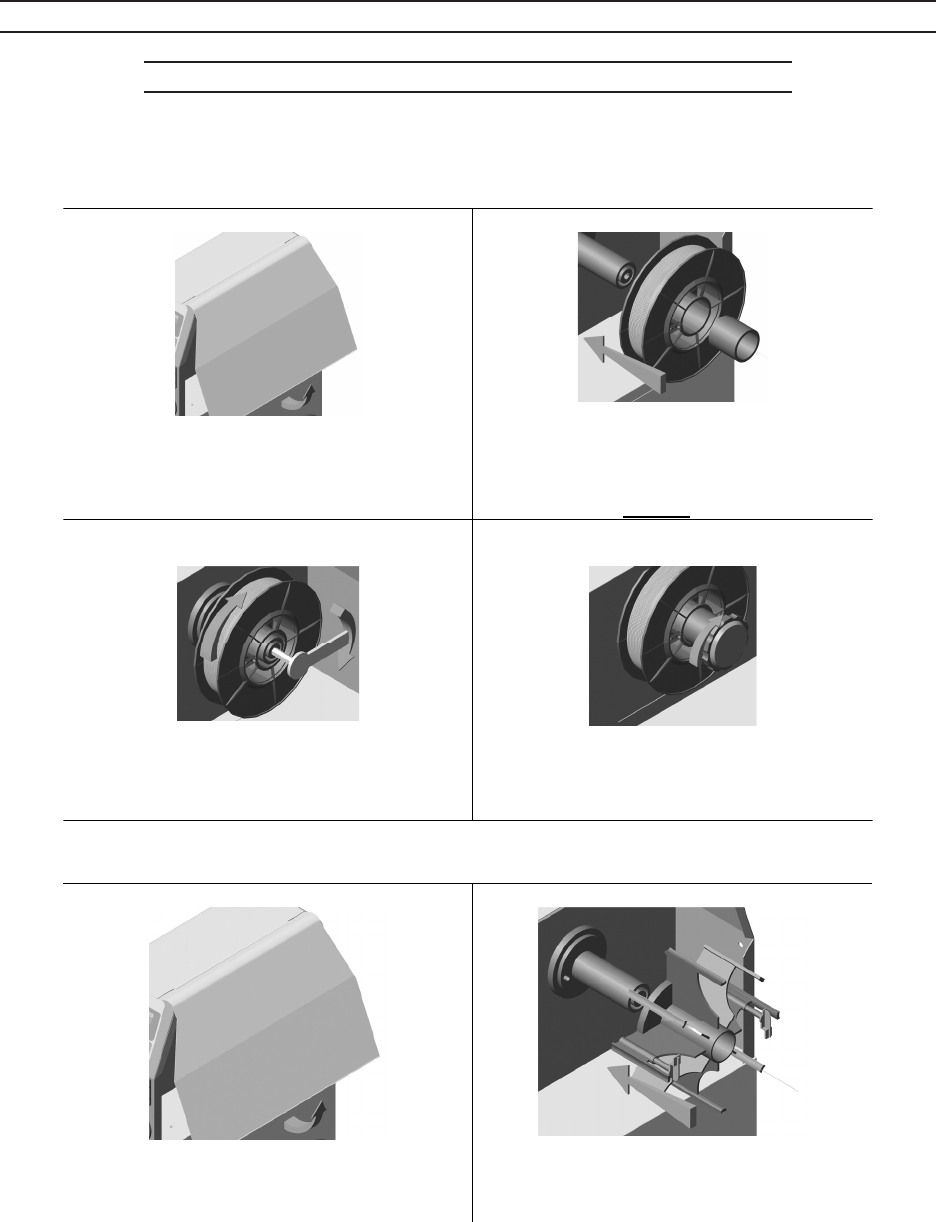
TO INSTALL THE WIRE SPOOL
Two variants to expose the Wire Drive Assembly are probable for Spool 200mm (variant A)
and for EN 759 Spool 300mm (variant B) use.
Variant A
1.
Lift the Door (14A) of the Welder to expose
the Wire Drive Assembly.
2.
Insert the Spool and the Pressing Cartridge
onto the Threaded Shaft (11A). Making
sure the Spool's Welding Wire unwinds
from the bottom (clockwise).
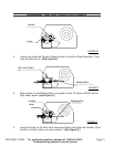
3.
When a slight force is needed to turn Spool,
tension is set.
4.
Screw the Fixing Cover into the Threaded
Shaft (11A).
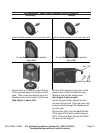
Variant B
1.
Lift the Door (14A) of the Welder to expose
the Wire Drive Assembly.
2.
Insert the Spool′s Holder onto the
Threaded Shaft (11A).
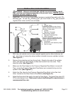
For use with a 11” Spool:
MIG&ARC 250 AMP - SKU 95424
MIG DUAL 250 AMP – SKU
For technical questions, please call 1-800-444-3353;
Troubleshooting section at end of manual.
Page 14
TO INSTALL THE WIRE SPOOL
Two variants to expose the Wire Drive Assembly are probable for Spool 200mm (variant A)
and for EN 759 Spool 300mm (variant B) use.
Variant A
1.
Lift the Door (14A) of the Welder to expose
the Wire Drive Assembly.
2.
Insert the Spool and the Pressing Cartridge
onto the Threaded Shaft (11A). Making
sure the Spool's Welding Wire unwinds
from the bottom (clockwise).
3.
When a slight force is needed to turn Spool,
tension is set.
4.
Screw the Fixing Cover into the Threaded
Shaft (11A).
Variant B
1.
Lift the Door (14A) of the Welder to expose
the Wire Drive Assembly.
2.
Insert the Spool′s Holder onto the
Threaded Shaft (11A).
ASSEMBLY INSTRUCTIONS (CONTINUED)