


For technical questions, please call 1-800-444-3353;
Troubleshooting section at end of manual.
Page 22SKU 95424, 95629
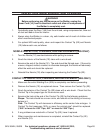
MIG WELDING SET UP
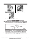
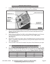
If using solid-core wire, connect and secure an Argon/ CO
2
gas hose to the rear of
the Welder. (If using flux core wire, protective gas is not required.)
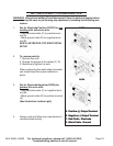
9. Make sure the Power Switch (1C) is in its “OFF” position. Then plug Power Cord (1A)
of the Welder into a dedicated, 230 VAC, 40 AMP line with delayed action type circuit
breaker or fuse. (See page 32.)
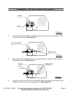
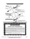
10. While holding the Welding Torch (10C), with the Welding Wire clearly out of the way of
any grounded objects, turn the Power Switch (1C) to its “ON” position.(See Figure G)
11. Momentarily squeeze the Trigger Switch (13E) of the to test the wire feed speed. If
necessary, adjust the speed by turning the Wire Feed Speed Knob (3C).
(See Figure G)
12. Orient yourself on the area to be welded, then place a Face Shield over your eyes.
WARNING! Never look at the ignited arc without ANSI-approved, arc-
shaded, eye protection in a full face shield. Permanent eye damage
or blindness can occur. Skin burns can occur. Never breathe arc
fumes.
13.
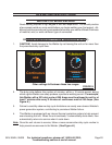
For switching in ARC mode Wire Feed Speed Knob (3C) in appropriate sector. Red
ELECTRODE WELDING INDICATOR (4C) will light up. (See Figure G)
14. NOTE: Welder MIG DUAL 250 AMP has no about the WIRE FEED SPEED KNOB
(3C) sector "Electrode" and ELECTRODE WELDING INDICATOR
(4C)
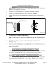
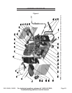
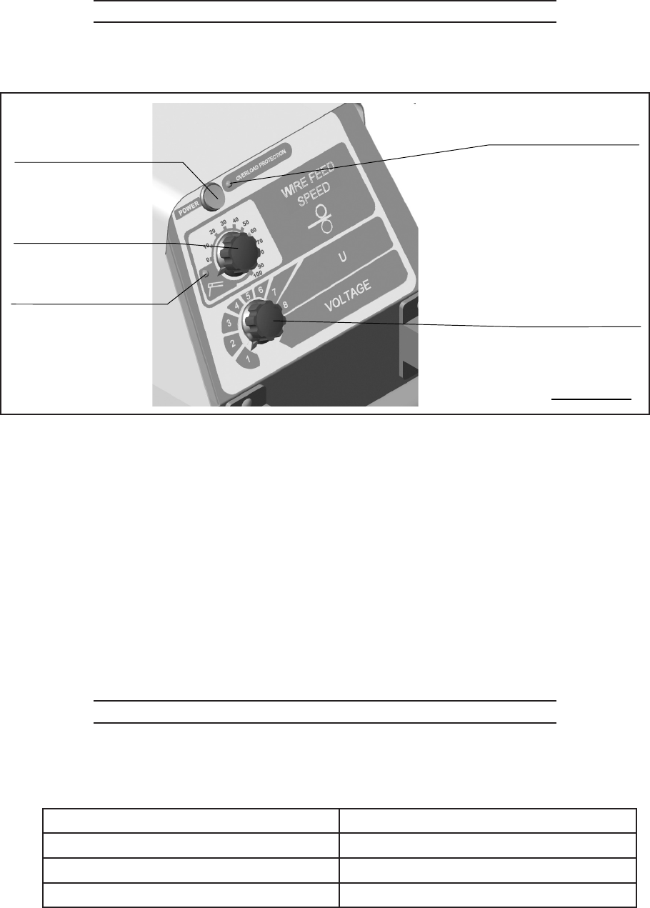
OVERLOAD PROTECTOR (2C)
POWER SWITCH (1C)
WIRE FEED
SPEED KNOB (3C)
ELECTRODE
WELDING
INDICATOR (4C)
VOLTAGE SELEC-
TOR KNOB (5C)
FIGURE K
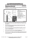
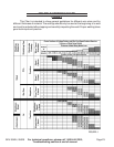
Set the desired welding voltage and wire speed for the thickness of metal being
welded, using the Voltage Selector Knob (5C) and Wire Feed Speed Knob (3C).
(See Figures K & J.)
While holding the Welding Gun (20A), with the Welding Wire clearly out of the way
of any grounded objects, turn the Power Switch (1C) to its “ON” position.
(See Figure K.)
Momentarily squeeze the Trigger (13E) of the Welding Torch to test the wire feed
speed. If necessary, adjust the speed by turning the Wire Speed Control Knob
(3C). (See Figure K.)
Orient yourself on the area to be welded, then place a Face Shield over your eyes.
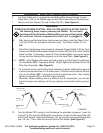
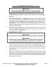
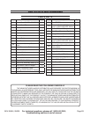
ARC (STICK) WELDING SET UP (FOR MODEL 95424 ONLY)
Turn the Wire Feed Speed Knob (3C) to the appropriate sector. The RED
Electrode Indicator (4C) will light up and the wire will not move. (See Figure
K.) Below are recommended positions of the Voltage Selector Knob (5C.)
Diameter of electrode Voltage Selector Knob position
1/16” 1-4
1/8” 3-6
3/16” 5-8
7.
8.
9.
10.
11.
12.