


For technical questions, please call 1-800-444-3353;
Troubleshooting section at end of manual.
Page 15SKU 95424, 95629
ASSEMBLY INSTRUCTIONS (CONTINUED)
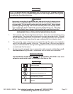
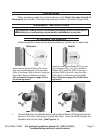
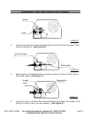
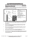
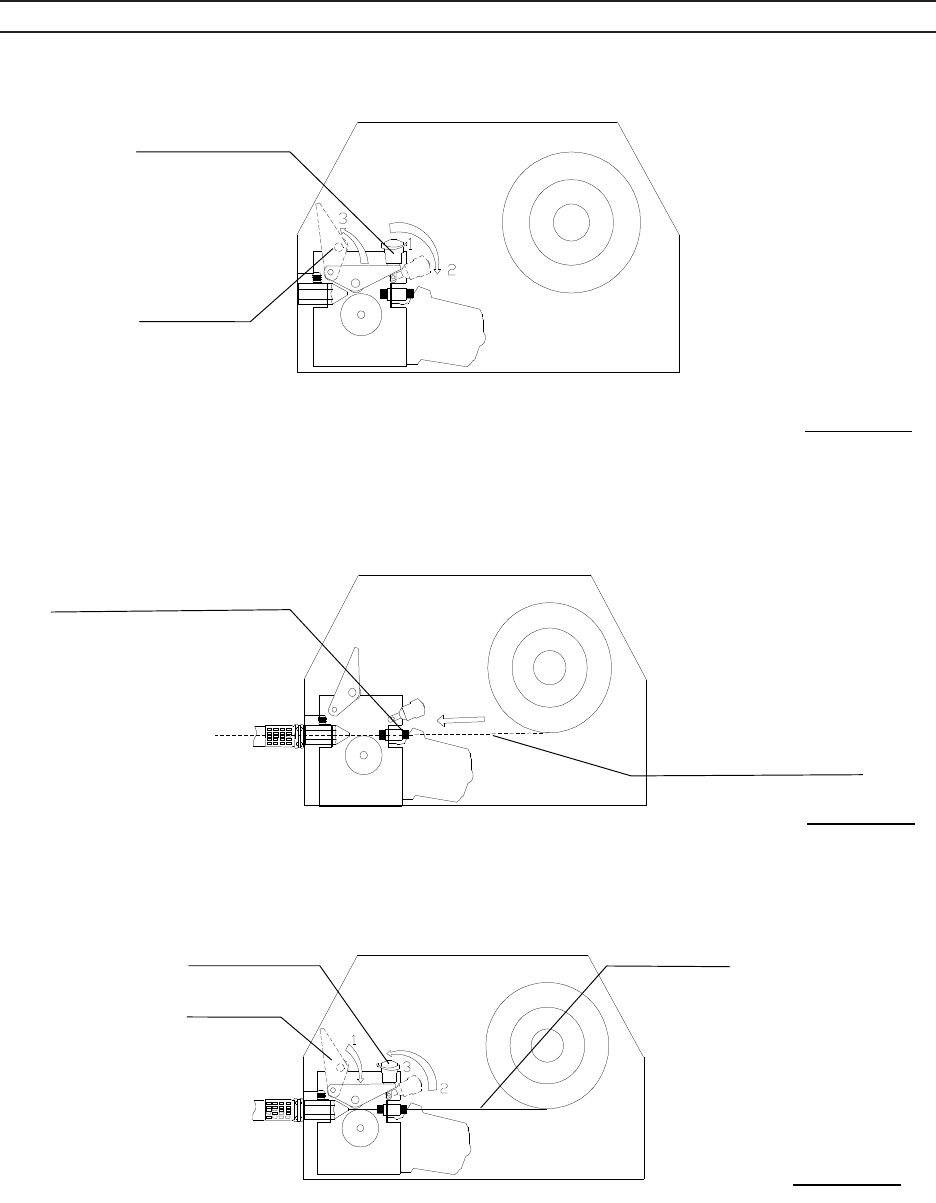
3. Loosen, and lower the Handle (4D) on the Wire Drive Assembly. Then, raise the
Lever (3D). (See Figure B)
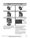
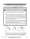
4. Keep tension on the Wire, and guide at least 12 inches of Wire into the Wire Inlet
Guide. (See Figure C)
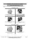
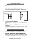
5. Lower the Lever (3D) on the Wire Drive Assembly. Raise and tighten the
Handle (4D). Once the Wire is held in place, you may release it. (See Figure D)
Handle
Lever
FIGURE B
Wire Inlet Guide
Welding Wire
FIGURE C
Handle Welding Wire
Lever
FIGURE D
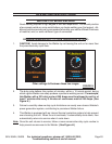
Loosen and lower the Tension Adjusting Knob on the Wire Feed Assembly. Then,
raise the Swing Arm. (See Figure B.)
MIG&ARC 250 AMP - SKU 95424
MIG DUAL 250 AMP – SKU
For technical questions, please call 1-800-444-3353;
Troubleshooting section at end of manual.
Page 16
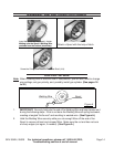
3. Loosen, and lower the Handle (4D) on the Wire Drive Assembly. Then, raise the
Lever (3D). (See Figure B)
4. Keep tension on the Wire, and guide at least 12 inches of Wire into the Wire Inlet
Guide. (See Figure C)
5. Lower the Lever (3D) on the Wire Drive Assembly. Raise and tighten the
Handle (4D). Once the Wire is held in place, you may release it. (See Figure D)
Handle (4D)
Lever (3D)
FIGURE B
Wire Inlet Guide
Welding Wire
FIGURE C
Handle (4D) Welding Wire
Lever (3D)
FIGURE D
Keep tension on the Welding Wire, and guide at least 12 inches of Wire into the
Wire Feed Leader. (See Figure C.)
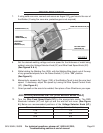
3. Loosen, and lower the Handle (4D) on the Wire Drive Assembly. Then, raise the
Lever (3D). (See Figure B)
4. Keep tension on the Wire, and guide at least 12 inches of Wire into the Wire Inlet
Guide. (See Figure C)
5. Lower the Lever (3D) on the Wire Drive Assembly. Raise and tighten the
Handle (4D). Once the Wire is held in place, you may release it. (See Figure D)
Handle
Lever
FIGURE B
Wire Inlet Guide
Welding Wire
FIGURE C
Handle Welding Wire
Lever
FIGURE D
Lower the Level on the Wire Drive Assembly. Raise and tighten the Handle. Once
the Wire is held in place, you may release it. (See Figure D.)
3.
4.
5.