


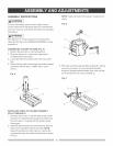
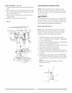
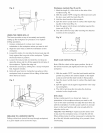
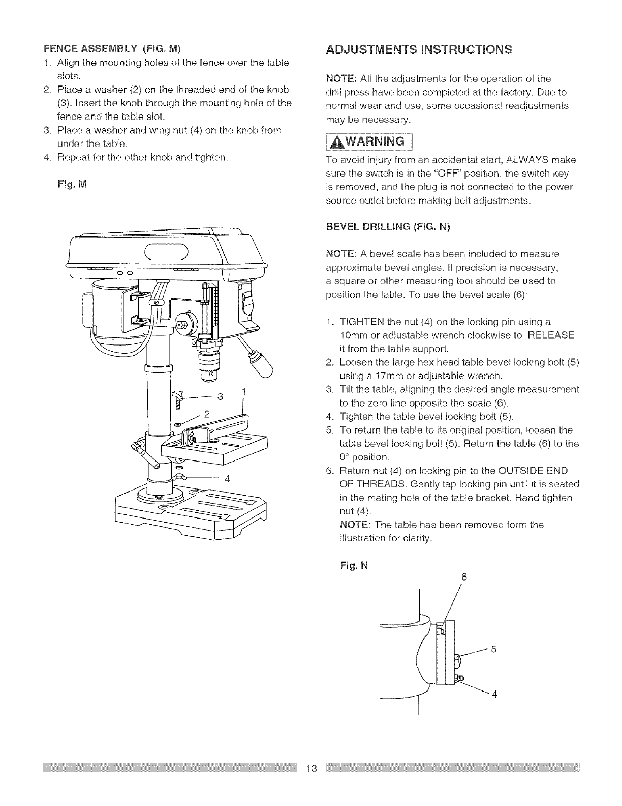
FENCE ASSEMBLY (FIG. M)
1_ Align the mounting holes of the fence over the table
slots.
2. Place a washer (2) on the threaded end of the knob
(3). Insert the knob through the mounting hole of the
fence and the table slot.
3. Place a washer and wing nut (4) on the knob from
under the table.
4. Repeat for the other knob and tighten.
Fig. M
ADJUSTMENTS mNSTRUCTmONS
NOTE: All the adjustments for the operation of the
drill press have been completed at the factory. Due to
normal wear and use, some occasional readjustments
may be necessary.
[a,WARNmNG]
To avoid injury from an accidenta! start, ALWAYS make
sure the switch is in the "OFF" position, the switch key
is removed, and the plug is not connected to the power
source outlet before making belt adjustments.
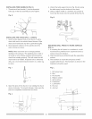
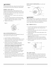
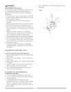
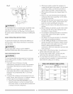
BEVEL DRILLING (FIG. N)
NOTE: A bevel scale has been included to measure
approximate bevel angle& If precision is necessary,
a square or other measuring tool should be used to
position the table. To use the bevel scale (6):
1. TIGHTEN the nut (4) on the locking pin using a
10mm or adjustable wrench clockwise to RELEASE
it from the table support.
2. Loosen the large hex head table bevel locking bolt (5)
using a 17ram or adjustable wrench.
3. Tilt the table, aligning the desired angle measurement
to the zero line opposite the scale (6).
4. Tighten the table bevel locking bolt (5).
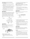
5. To return the table to its original position, loosen the
table bevel locking bolt (5). Return the table (6) to the
0° position.
6. Return nut (4) on locking pin to the OUTSIDE END
OF THREADS. Gently tap locking pin until it is seated
in the mating hole of the table brackeL Hand tighten
nut (4).
NOTE: The table has been removed form the
illustration for clarity_
Fig. N
J
6
13