


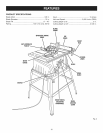

OPERATING COMPONENTS
The upper portion of the blade projects up through the
table and issurrounded by an insert called the throat
plate. The height of the blade isset with a handwheel on
the front of the cabinet. To accommodate wide panels, the
saw table has rails on each side. Detailed instructions are
provided in the Operation section of this manual for the _1_
basic cuts: cross cuts, miter cuts, bevel cuts, and com-
pound cuts.
The rip fence is used to position work for lengthwise cuts.
A scale on the front rail shows the distance between the
rip fence and the blade.
It is very important to use the blade guard assembly for all
A
through-sawing operations. The blade guard assembly
includes: riving knife/spreader/splitter, anti-kickback
pawls, and plastic blade guard.
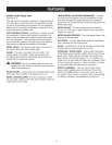
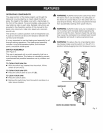
SWITCH ASSEMBLY
See Figure 3.
This saw is equipped with a switch assembly that has a
built-in locking feature. This feature is intended to prevent
unauthorized and possible hazardous use by children and
others.
TO TURN YOUR SAW ON:
[] With the switch key inserted into the switch, lift the
switch to turn on ( I }.
TO TURN YOUR SAW OFF:
[] Press the switch down to turn off ( O ).
TO LOCK YOUR SAW:
[] Press the switch down.
[] Remove the switch key from the switch and store in a
safe, secure location.
WARNING: ALWAYS remove the switch key when
the tool isnot in use and keep it in a safe place. In
the event of a power failure, turn the switch off ( O )
and remove the key. This action will prevent the tool
from accidentally starting when power returns.
WARNING: ALWAYS make sure your workpiece is
not in contact with the blade before operating the
switch to start the tool. Failure to heed this warning
may cause the workpiece to be kicked back toward
the operator and result in serious personal injury.
WARNING: To reduce the risk of accidental start-
ing, Always make sure the switch is in the off ( O )
position before plugging tool into the power source.
SWITCH SWITCH
ON OFF
SWITCHKEY
SWITCHIN LOCKEDPOSITION
Fig. 3
12