


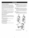
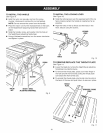

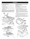
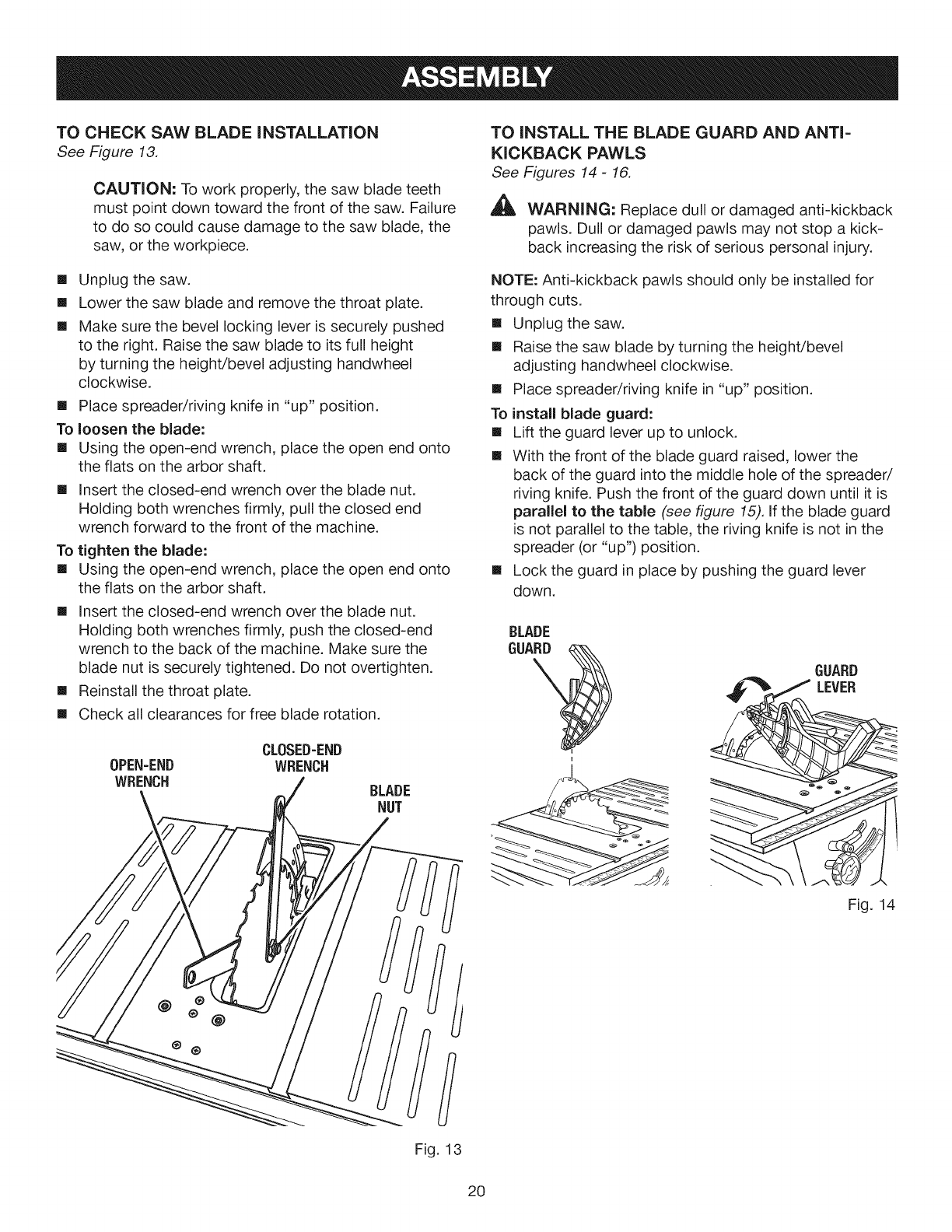
TO CHECK SAW BLADE iNSTALLATiON
See Figure 13.
CAUTION: To work properly, the saw blade teeth
must point down toward the front of the saw. Failure
to do so could cause damage to the saw blade, the
saw, or the workpiece.
[]
[]
[]
Unplug the saw.
Lower the saw blade and remove the throat plate.
Make sure the bevel locking lever is securely pushed
to the right. Raise the saw blade to its full height
by turning the height/bevel adjusting handwheel
clockwise.
[] Place spreader/riving knife in "up" position.
To loosen the blade:
[] Using the open-end wrench, place the open end onto
the flats on the arbor shaft.
[] Insert the closed-end wrench over the blade nut.
Holding both wrenches firmly, pull the closed end
wrench forward to the front of the machine.
To tighten the blade:
[] Using the open-end wrench, place the open end onto
the flats on the arbor shaft.
[] Insert the closed-end wrench over the blade nut.
Holding both wrenches firmly, push the closed-end
wrench to the back of the machine. Make sure the
blade nut is securely tightened. Do not overtighten.
[] Reinstall the throat plate.
[] Check all clearances for free blade rotation.
0PEN-END
WRENCH
CLOSED=END
WRENCH
BLADE
NUT
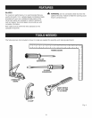
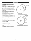
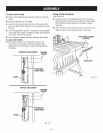
TO INSTALL THE BLADE GUARD AND ANTI-
KICKBACK PAWLS
See Figures 14- 16.
WARNING: Replace dull or damaged anti-kickback
pawls. Dull or damaged pawls may not stop a kick-
back increasing the risk of serious personal injury.
NOTE: Anti-kickback pawls should only be installed for
through cuts.
[] Unplug the saw.
[] Raise the saw blade by turning the height/bevel
adjusting handwheel clockwise.
[] Place spreader/riving knife in "up" position.
To install blade guard:
[] Lift the guard lever up to unlock.
[] With the front of the blade guard raised, lower the
back of the guard into the middle hole of the spreader/
riving knife. Push the front of the guard down until it is
parallel to the table (see figure 15). If the blade guard
is not parallel to the table, the riving knife is not in the
spreader (or "up") position.
[] Lock the guard in place by pushing the guard lever
down.
BLADE
GUARD
GUARD
LEVER
Fig. 14
Fig. 13
20