


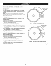
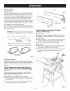
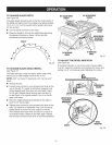
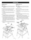

TO CHANGE BLADE DEPTH
See Figure 26.
The blade depth should be set so that the outer points of
the blade are higher than the workpiece by approximately
1/8 in. to 1/4 in. but the lowest points (gullets) are below
the top surface.
[] Turn the bevel lock lever to the right.
[] Raise the blade by turning the height/bevel adjusting
handwheel clockwise or lower it by turning the
handwheel counterclockwise.
GULLET
Fig. 26
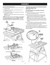
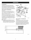
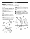
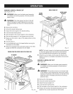
TO CHANGE BLADE ANGLE (BEVEL)
See Figure 27.
This table saw has a rack and pinion bevel control that
allows you to make angled cuts from 90° to 45 °.
NOTE: A 90 ° cut has a 0° bevel and a 45° cut has a 45 °
bevel.
[] Unplug the saw.
[] Loosen bevel control by turning bevel lock lever all the
way to the left. If it needs to be further loosened, pull
spring-loaded bevel lock lever out and rotate it back
to the right. Release bevel locking lever and allow it
to seat (lock) in its original position. Turn it to the left
again until loose.
[] Move the height adjusting handwheel to the right to
bevel to 45° bevel angle.
[] Tighten bevel control by turning bevel lock lever to the
right. If it needs to be tightened more, pull the spring-
loaded bevel lock lever out and rotate it to the left.
Then release bevel lock lever and allow it to return to
its original position. Rotate to the right again. Repeat
this process until bevel lock lever is securely tightened.
900ADJUSTMENT 450ADJUSTMENT
SCREW SCREW
TODECREASE
ANGLE
BEVEL
LEVER
HEIGHT/BEVEL
ADJUSTING
HANDWHEEL
TOINCREASE
ANGLE
Fig. 27
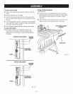
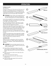
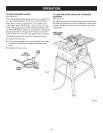
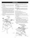
TO ADJUST THE BEVEL INDICATOR
See Figure 28.
If the bevel indicator is not at zero when the saw blade
is at 90 °, adjust the indicator by loosening the screw and
setting it at 0° on the bevel scale. Retighten the screw.
COMBINATION
SQUARE
HEIGHT/BEVEL
ADJUSTING
HANDWHEEL
BEVEL
LOCKING
LEVER
SCREW
BEVEL
iNDiCATOR
Fig. 28
27