


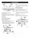

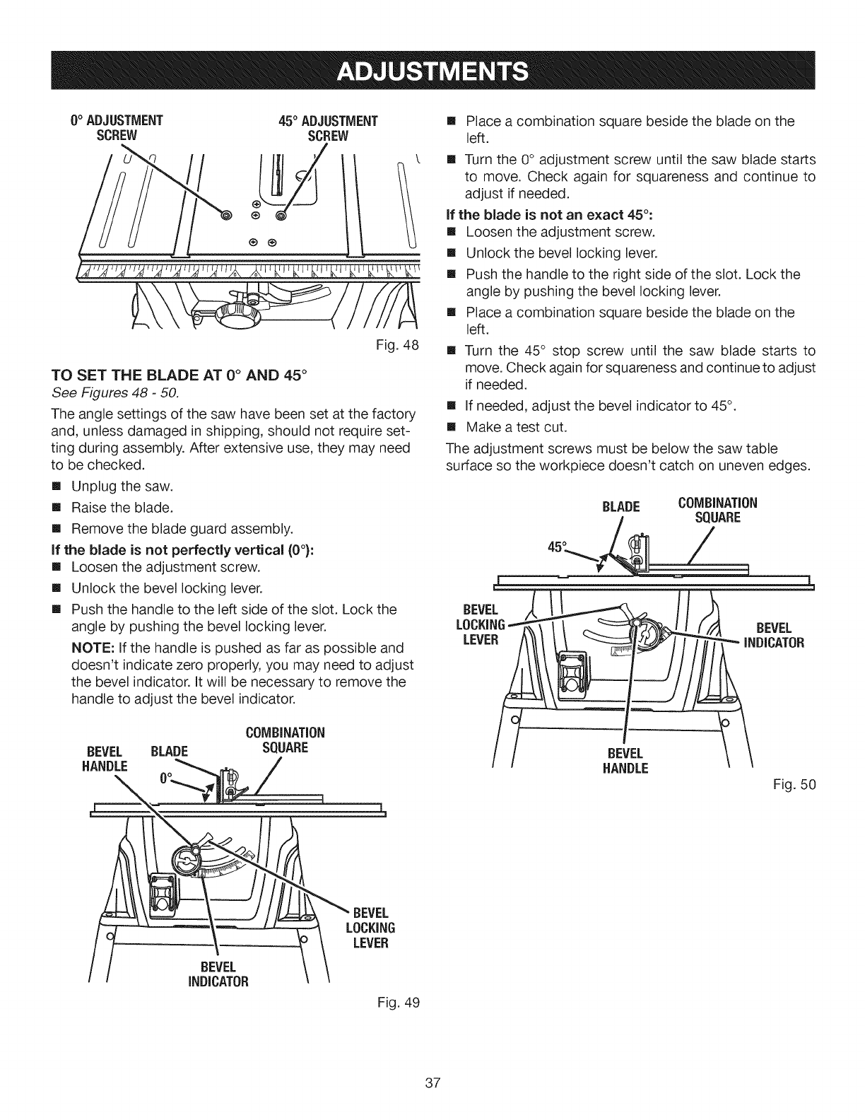
0° ADJUSTMENT 45° ADJUSTMENT
SCREW SCREW
®
Fig. 48
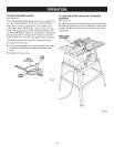
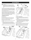
TO SET THE BLADE AT 0° AND 45 °
See Figures 48 - 50.
The angle settings of the saw have been set at the factory
and, unless damaged in shipping, should not require set-
ting during assembly. After extensive use, they may need
to be checked.
[] Unplug the saw.
[] Raisethe blade.
[] Remove the blade guard assembly.
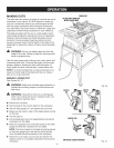
if the blade is not perfectly vertical (0°):
[] Loosen the adjustment screw.
[] Unlock the bevel locking lever.
[] Push the handle to the left side of the slot. Lock the
angle by pushing the bevel locking lever.
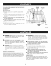
NOTE: If the handle is pushed as far as possible and
doesn't indicate zero properly, you may need to adjust
the bevel indicator. It will be necessary to remove the
handle to adjust the bevel indicator.
BEVEL BLADE
HANDLE
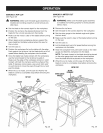
[] Place a combination square beside the blade on the
left.
[] Turn the 0° adjustment screw until the saw blade starts
to move. Check again for squareness and continue to
adjust if needed.
if the blade is not an exact 45°:
[] Loosen the adjustment screw.
[] Unlock the bevel locking lever.
[] Push the handle to the right side of the slot. Lock the
angle by pushing the bevel locking lever.
[] Place a combination square beside the blade on the
left.
[] Turn the 45° stop screw until the saw blade starts to
move. Check again for squareness and continue to adjust
if needed.
[] If needed, adjust the bevel indicator to 45°.
[] Make a test cut.
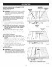
The adjustment screws must be below the saw table
surface so the workpiece doesn't catch on uneven edges.
L
BEVEL
HANDLE
BEVEL
"" INDICATOR
Fig. 50
BEVEL
INDICATOR
BEVEL
LOCKING
LEVER
Fig. 49
37