


11
Fig. 16A
C
A
Fig. 16
D
A
D
C
B
A
B
C
D
E
G
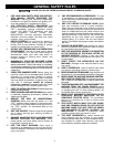
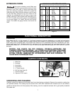
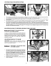
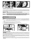
1. The compound miter saw will cut any angle from a straight 0° cut to 48° right and left. Turn the locking knob (A) Fig.
13 counterclockwise, depress the lock lever (B), and rotate the table to the desired position.
2. This machine is equipped with positive stops at the 0° cut-off position and at the 15°, 22.5°, 31.6°, and 45° left and
right positions.
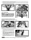
3. The center line (C) Fig. 14 on the cursor indicates the actual angle of cut. Each scale line (B) represents 1°. When
the center line (C) is moved from one line to the next on the scale, the angle of the cut is changed by 1°.
4. The pointer is provided with two additional lines (D) and (E), Fig. 14. This allows movement of the control arm by
exactly 1/2°. For example, assume that the center line (C) is pointing to the 10° mark on the scale, as indicated, and
the desired angle of cut is 1/2° to the right. Move the control arm until the right line (E) lines up with the next line on
the scale. The angle of cut will then be changed 1/2° to the right. If you change the angle of cut 1/2° to the left, use
the left line (D) in the same manner.
F
F
ROTATING TABLE FOR MITER CUTTING
Fig. 13
Fig. 14
DISCONNECT THE MACHINE FROM
THE POWER SOURCE.
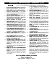
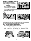
Fig. 15
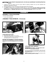
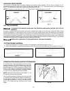
To adjust the sliding fit between the movable table and
the base, turn the nut (A) Fig. 15 clockwise to tighten the
fit (counter-clockwise to loosen the fit). This adjustment
should not be so tight that it restricts the rotating
movement of the table, or so loose that it affects the
accuracy of the saw.
ADJUSTING SLIDING FIT BETWEEN MOVABLE TABLE AND BASE
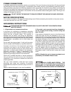
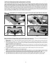
ADJUSTING FENCE 90° TO BLADE
IMPORTANT: before making this adjustment, SET the
blade at 0° to the table. (See section “Adjusting 0°, 33.9°,
and 45° bevel positive stops”.)
A
DISCONNECT THE MACHINE FROM
THE POWER SOURCE.
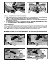
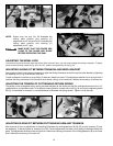
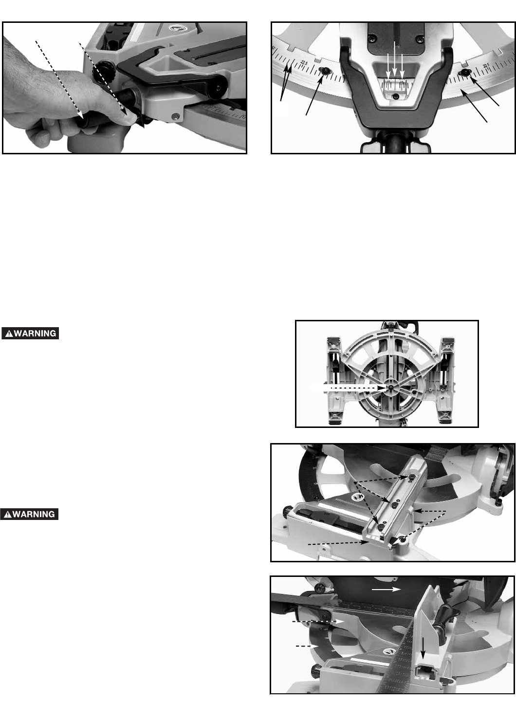
1. The right fence base (A) Fig. 16 is properly aligned at
the factory. However, should adjustment of the right
fence be necessary, loosen the bolts (D) and position
the base (A) against the shoulders (C). Tighten the
bolts (D) securely. NOTE: The right side sliding fence
segment has been removed for this illustration.
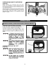
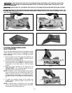
2. Rotate the movable table (A) Fig. 16A so that the
blade (C) is 90° to the right fence .
3. Adjust the front miter scale (B) Fig. 16A so that the 0°
notch is engaged.
B