


Fig. 33
C
A
Fig. 34
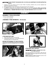
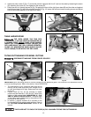
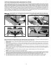
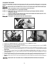
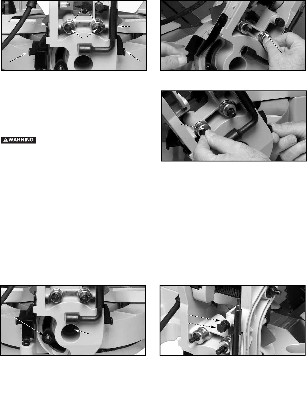
After a period of time, an adjustment of the sliding fit between the cuttinghead arm (B) Fig. 35, and the trunnion (C) may
be necessary. To adjust, tighten or loosen the nut (D). Correct adjustment provides a snug sliding fit between these two
parts. This adjustment should not be so tight that it restricts the sliding movement of the cuttinghead arm (B) or so loose
that it affects the accuracy of the saw cut.
B
14
Fig. 30
Fig. 29
A
A
C
B
C
D
D
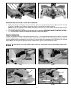
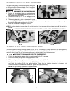
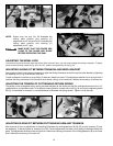
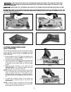
Shown from the rear, Fig. 30 illustrates the
sliding plate position and bushing (C)
adjustment for 45° left and Fig. 31 illustrates the
sliding plate position and bushing (C)
adjustment for 45° right.
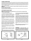
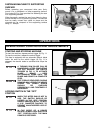
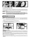
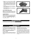
ADJUSTING SLIDING FIT BETWEEN TRUNNION AND BEVEL BRACKET
After a period of time, it may become necessary to adjust the sliding fit between the trunnion and the bevel bracket by tightening
the adjusting nut (C) Fig. 33 at the rear of the tool.
Correct adjustment provides a snug sliding fit between these two parts. This adjustment should not be so tight that it
restricts the tilting movement of the trunnion when bevel cutting, or so loose that it affects the accuracy of the saw cut.
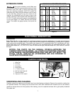
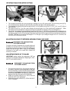
ADJUSTING THE TENSION OF CUTTINGHEAD RETURN SPRING
The tension of the cuttinghead return spring has been adjusted at the factory so that the cuttinghead returns to the “up”
position after a cut has been made. To re-adjust the spring tension, loosen the nut (A) Fig. 34 and turn the adjusting screw
(B) Fig. 34 clockwise to increase, or counterclockwise to decrease the spring tension. Tighten nut (A) securely.
MAKE SURE THAT THE FENCES ARE
CLEAR OF THE GUARD AND BLADE
BEFORE OPERATING THE SAW.
NOTE:
ADJUSTING SLIDING FIT BETWEEN CUTTINGHEAD ARM AND TRUNNION
C
Fig. 31
A
ADJUSTING THE BEVEL LOCK
The bevel-locking force has been set at the factory. After a period of time, you may need to adjust the locking mechanism. To adjust,
place the bevel-locking handle (A) Fig. 28 in the “UP” position and tighten the nut (A) Fig. 33.