


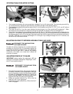
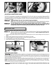
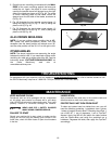
TAKE CARE NOT TO PINCH THE CORD (A) FIG. 23A WHEN TILTING THE CUTTINGHEAD.
IMPORTANT: Move the sliding fences to provide clearance for the blade and guard. The DEGREE of tilt determines how far
to move the sliding fences. Refer to the section “fence OPERATION.”
Fig. 22
12
Fig. 18
Fig. 21
A
A
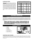
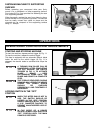
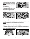
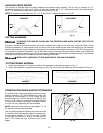
TABLE HAZARD ZONE
THE AREA INSIDE THE TWO RED
LINES (A) FIG. 21 ON THE TABLE IS DESIGNATED AS
A HAZARD ZONE. NEVER
PLACE YOUR HAND(S)
INSIDE THE "TABLE HAZARD ZONE" (WITHIN THE
RED LINES) WHILE THE TOOL IS BEING OPERATED.
CLAMP ALL WORKPIECES WHICH WOULD CAUSE
YOUR HAND(S) TO BE WITHIN THE RED LINES.
Fig. 17
Fig. 23
A
G
F
A
B
D
C
B
A
C
D
Fig. 23A
A
H
TILTING CUTTINGHEAD FOR BEVEL CUTTING
DISCONNECT MACHINE FROM POWER SOURCE.
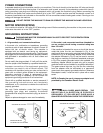
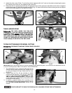
4. Adjust the miter curser (F) Fig. 17 so that the pointer is aligned with the 0° mark on the scale by loosening the screw
(G), adjusting the cursor (F), and tightening the screw (G).
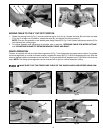
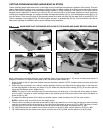
5. Place one end of a framing square (A) Fig. 18 against the front of the right fence base (B) and the other end against
the left fence base (C). Using the supplied wrench (D) Fig. 18, loosen the left fence base mounting screws and adjust
the left fence base parallel to the right fence base.
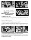
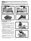
1. The cuttinghead of your compound miter saw can be
tilted to cut any bevel angle from a 90° straight cut-off
to a 48° bevel angle left or right. Raise bevel lock lever
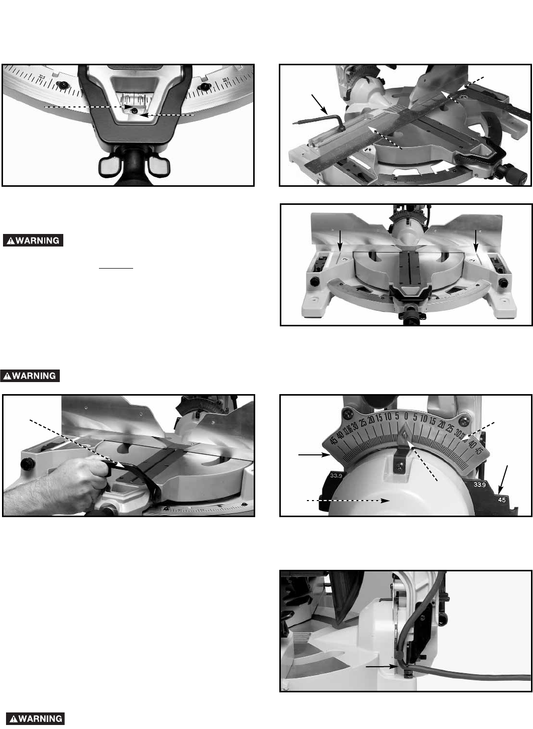
(A) Fig. 22.
2. Positive stops (A) Fig. 23 are provided to rapidly
position the saw blade at 0°, 33.9° and 45°. Refer to the
section of this manual titled “ADJUSTING 0°, 33.9°
AND 45° BEVEL POSITIVE STOPS.” The bevel angle
of the cutting head is determined by the position of the
pointer (B) on the scale (C).
3. In addition, a marked indicator (D) is provided on the
bevel scale (33.9°) for cutting crown moulding. Refer to
the “CUTTING CROWN MOULDING” section of this
manual.