


13
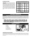
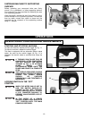
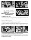
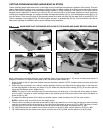
The bevel setting feature utilizes a sliding plate (A) Fig. 24,
pin (B), and bushing (C) design that is used to select the
bevel angle. The position of the pin (B) and the sliding plate
(A) determine the bevel angle.
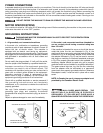
DISCONNECT THE MACHINE FROM THE
POWER SOURCE.
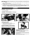
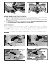
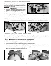
1. Position the bevel detent plate so that the desired
angle (A) Fig. 23 is exposed immediately to the left or
right of the housing (H) Fig. 23.
2. Lift the front handle (A) Fig. 22 to disengage bevel
lock.
3. Tilt the cuttinghead left or right as desired until it stops
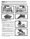
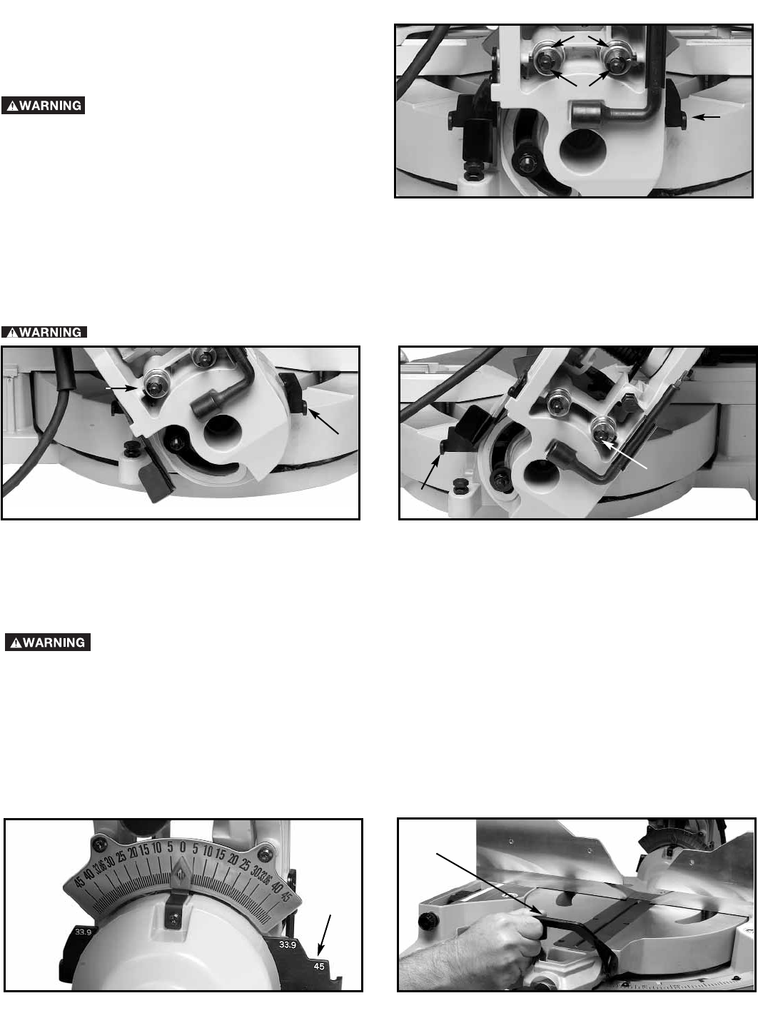
on plate (A) Fig. 23. NOTE: Shown from the rear, Fig. 25 illustrates the sliding plate positioned for 33.9° right and Fig. 26
illustrates the sliding plate positioned for 33.9° left.
4. Lower the front handle to engage the bevel lock.
NOTE: To perform a bevel cut of more than 45°, pull the bevel pin (B) out to bypass the bevel detent plate. 48° left or right is
possible.
Fig. 24
A
B
C
SELECTING 0°, 33.9°AND 45° BEVEL POSITIVE STOPS
MAKE SURE THAT THE FENCES ARE CLEAR OF THE GUARD AND BLADE BEFORE USING SAW.
Fig. 26
A
B
Fig. 25
A
B
Fig. 28
Fig. 27
A
A
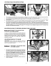
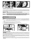
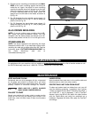
ADJUSTING 0°, 33.9°, AND 45° BEVEL POSITIVE STOPS
The bevel adjustment utilizes a sliding plate (A) Fig. 24, pin (B), and bushing (C) design feature that can be adjusted to
fine-adjust the bevel angle. The position of the pin within the bushing is adjustable and, when set, determines the bevel
angle. To adjust, loosen the pin locking screws, move to desired location, and tighten securely.
DISCONNECT THE MACHINE FROM THE POWER SOURCE.
1. Position the bevel detent plate so that the desired angle (A) Fig. 27 is exposed.
2. Lift the front handle (A) Fig. 28 to disengage the bevel lock.
3. Tilt the cuttinghead left or right as desired until it stops on the plate (A) Fig. 27.
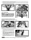
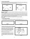
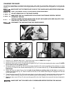
4. To adjust, loosen the pin locking set screw(s) (D) Fig. 29 (shown from the rear), located on the side of the trunnion
and rotate the bushing (C) to the desired location. Rotate the left bushing clockwise to increase and
counterclockwise to decrease the bevel angle. Tighten screw(s) (D) securely.
NOTE: The right bushing adjustment is opposite the left.