


17
Fig. 43
Fig. 44
Fig. 45
Fig. 46
A
B
A
D
A
B
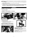
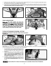
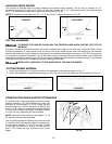
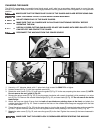
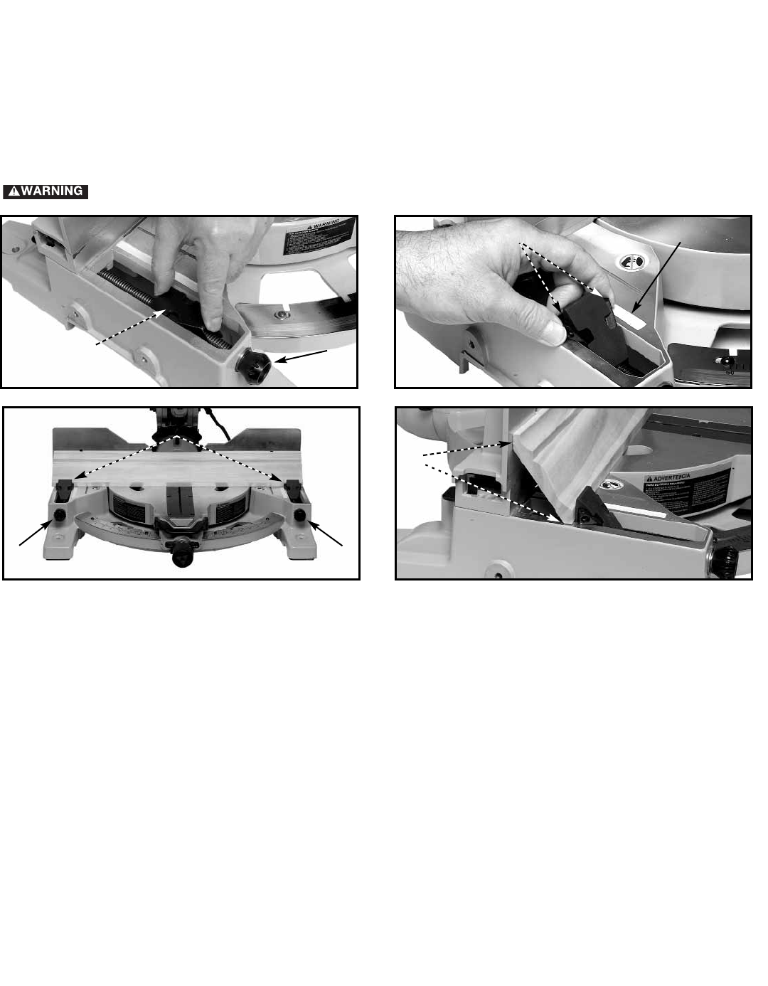
CUTTING CROWN MOULDING (USING BUILT-IN STOPS)
Crown moulding stops have been built in to the base to aid in holding the workpiece in position while cutting. This new
design feature allows cutting crown moulding in either the flat or nested position and utilizes a stop and screw feature
that can be quickly adjusted to accommodate several widths of crown moulding. The position of the stops can be
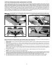
adjusted by two methods. To adjust, turn knob (A) Fig. 43 until stop (B) is in the proper position to mount the crown
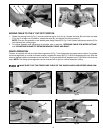
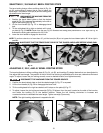
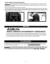
moulding at the selected angle, or, squeeze the ears and depress the stop (A) Fig. 44 to disengage the stop (B) Fig. 43
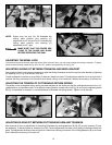
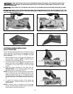
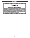
from the screw. Then move the stop to the desired location and raise the stop until the ears snap in place (B) Fig. 45.
Then if necessary turn knob(s) (A) Fig. 45 to fine adjust the stop. A recessed slot (D) Fig. 44 is provided for the user to
add pencil markings to establish various quick reference stop positions.
When cutting crown moulding using the crown moulding stops, do not bevel the cut. The crown moulding stop feature is
designed to make the cut with the cuttinghead at 90° and with the table rotated 45°.
1. Move the table to the 45° right miter position and lock the table in position. NOTE: A positive stop is provided to find this
angle quickly.
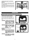
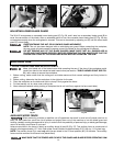
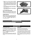
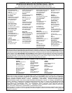
2. Place the crown moulding in the "nested" position between the fence and table with the ceiling edge on the base and
the wall edge against on the fence, as shown in Fig. 46. Make sure the flats of the molding, (D) Fig. 46, are even with the
fence and the table as shown. Make the cut.
NOTE: The piece of crown moulding used for the inside corner will always be on the right side of the blade, as shown
at (A) Fig. 46A. The piece of crown moulding used for the outside corner will always be on the left side of the blade, as
shown at (B) Fig. 46A.
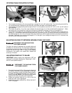
4. To make the matching halves of the inside and outside corners, rotate the table to the 45° left miter position.
NOTE: A positive stop is provided to find this angle quickly.
5. Place the crown moulding on the table as described in step 2 and make the cut. In this case, the piece of crown moulding
used for the outside corner will always be on the right side of the blade, as shown at (C) Fig. 46B. The piece of crown
moulding used for the inside corner will always be on the left side of the blade, as shown at (D) Fig. 46B.
6. Fig. 46C illustrates the two outside corner pieces; the piece cut at (B) Fig. 46A, and the piece cut at (C) Fig. 46B.
7. Fig. 46D illustrates the two inside corner pieces; the piece cut at (D) Fig. 46B, and the piece cut at (A) Fig. 46A.
A
MAKE SURE THAT THE FENCES ARE CLEAR OF THE GUARD AND BLADE BEFORE USING SAW.
D