


12 - English
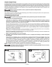
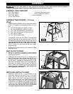
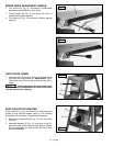
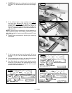
INFEED TABLE ADJUSTMENT HANDLE
1. Turn lock nut (C) Fig. 12, clock wise on infeed table
ad just ment handle (B) as far as it will go.
2. Thread handle (B) Fig. 12, into block (D) which is
located below infeed table (E).
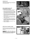
3. Turn locknut (C) Fig. 13 clockwise to tighten against
block (D).
E
D
C
B
C
D
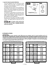
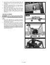
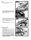
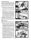
DUST CHUTE COVER
1. Assemble dust chute cover (A) Fig. 14, to dust chute
(B) using two wing screws (C). IMPORTANT: Top of
dust chute cover (A) must be inside top brace (D) of
stand.
During operation, the dust chute cover
(A) must always be assembled as shown and should
only be removed for cleaning.
B
C
C
A
D
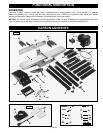
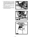
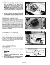
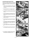
DUST COLLECTOR ADAPTER
If the machine is to be connected to a dust collection
system, a dust collector adapter with a 4" O.D. opening
is supplied with the jointer. To assemble the adapter:
1. Remove two wing screws (C) Fig. 14, from dust chute
cover (A).
2. Assemble adapter (E) Fig. 15, over dust chute (A).
Align two holes in dust chute (A) with holes in adapter
(E) and fasten with two wing screws (C) which were
removed in STEP 1.
Fig. 12
Fig. 13
Fig. 14
C
E
C
A
Fig. 15