


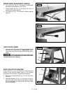


16 - English
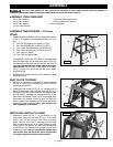
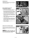
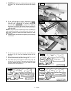
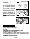
2. NOTE: When raising or lowering the infeed
table a plunger located on other end of
the index stop (C) Fig. 36, automatically
stops the table at 1/8 inch depth of cut.
To move the table past this point it is necessary to pull
out index stop (C) and move the table up or down.
IMPORTANT: Always make sure table lockhandle (A)
is tightened before op er a tion. The table lockhandle
(A) is spring-loaded and can be repositioned by
pulling out the handle and repositioning it on the
serrated nut located under the handle.
3. The depth of cut of the infeed table (position of table
in relationship with the cutting circle) can be read with
the pointer (D) Fig. 36, and scale (E). Maximum table
depth adjustment with this 6" jointer is 1/2 inch.
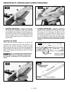
INFEED TABLE POSITIVE STOPS
Positive stops are provided to limit the height and depth of
the infeed table. To adjust the stops, loosen two locknuts
(F) and (G) Fig. 37, and turn the two adjusting screws (J)
and (K) as required. Then retighten the locknuts (F) and
(G). A good suggestion is to set the upper positive stop
(J) for your finish or final cut. This means that you will be
able to rapidly set the infeed table for a finish or final cut
without checking the scale and pointer. Also the lower
positive stop (K) can be set for the maximum 1/2" depth
of cut or if you desire to limit the depth of cut, adjust the
stop screw (K) accordingly.
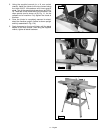
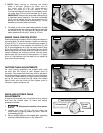
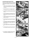
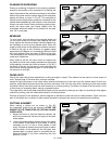
OUTFEED TABLE ADJUSTMENTS
For most jointing operations the outfeed table must
be level with the knives at their highest point of
revolution. This means that the knives must be parallel to
the outfeed table and project equally from the cutterhead.
To move the outfeed table up or down, loosen lockscrew
(A) Fig. 38, and turn hand knob (B). When the outfeed
table is level with the knives at their highest point of
revolution, tighten lockscrew (A).
A
B
F
K
G
J
D
E
A
C
Fig. 36
Fig. 37
Fig. 38
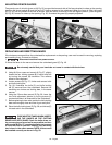
KNIFE AND OUTFEED TABLE
ADJUSTMENTS
In order to do accurate work, the knives must be exactly
level with the outfeed table. To check and adjust,
proceed as follows:
1. Disconnect machine from power
source.
2. Loosen lock lever (A) Fig. 40, and lower the
infeed table by pushing handle (B) down. Remove
cutterhead guard (C).
3. Place a straight edge on the outfeed table, extending
over the cutterhead as shown in Fig. 39 and 42.
STEEL STRAIGHT EDGE
OUT-FEED TABLE
IN-FEED
TABLE
CUTTER
Fig. 39