


14 - English
FENCE
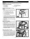
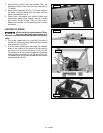
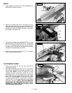
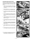
1. Insert hexagon rod (A) Fig. 20, of fence assembly into
bracket (B) on jointer as shown.
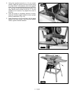
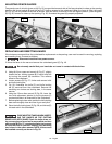
2. Remove the M8x1.25x12mm long screw (D) and
M8.4 flat washer (E) from the end of hexagon rod.
Assemble rear cutterhead guard (C) Fig. 21, to end of
hexagon rod using the M8x1.25x12mm long screw
(D) and M8.4 flat washer (E).
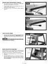
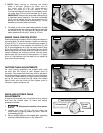
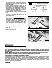
3. Thread fence locking handle assembly (F) Fig. 22, and
M8.4 flat washer (G) into hole (Z) Fig. 21. Lock handle
(F) Fig. 22, is spring-loaded and can be repositioned
by pulling out the handle and repositioning it onto the
serrated nut located under the handle.
4. Thread fence tilting handle (H) Fig. 22, to threaded
hole in back of fence as shown.
A
B
H
F
G
Z
C
E
D
Fig. 20
Fig. 21
Fig. 22
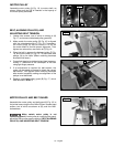
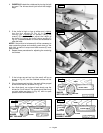
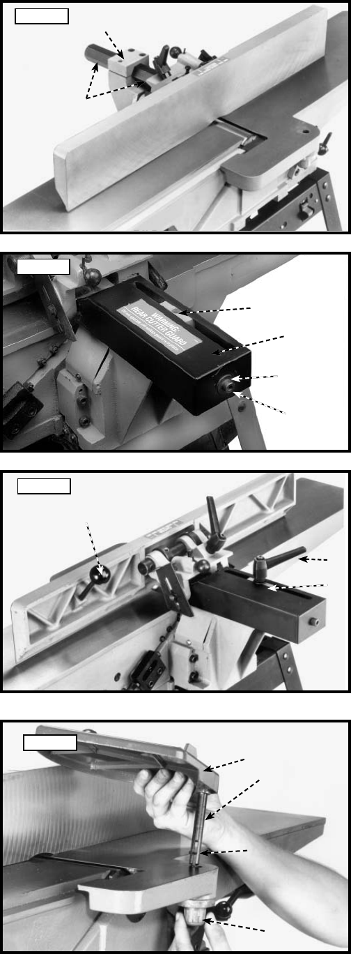
1. Remove set screw (A) Fig. 23, from post (B) of
cutterhead guard (C).
2. Assemble cutterhead guard (C) Fig. 23, to the jointer
by inserting post (B) down through the hole in the
infeed table. NOTE: A spring is supplied in knob
assembly (D) that returns the guard (C) over the
cutterhead after a cut has been made. Turn knob
(D) to tension spring before inserting post (B). Make
certain the spring engages in the slot of the post.
To adjust spring tension, remove the cutterhead
guard (C) Fig. 23, and rotate knob (D) to the desired
amount of tension. NOTE: THE CUTTERHEAD
GUARD MUST BE TENSIONED SO THAT IT WILL
RETURN TO COVER THE CUTTERHEAD ONCE
THE MATERIAL HAS PASSED.
CUTTERHEAD GUARD
B
A
D
C
Fig. 23