


9 - English
ASSEMBLY
ASSEMBLY TOOLS REQUIRED
ASSEMBLY TIME ESTIMATE - 2-3 hours
* 6mm Allen Wrench
* 4mm Allen Wrench
* 3mm Allen Wrench
* 2.5mm Allen Wrench
* 12x14mm Open End Wrench
* 8x10mm Open End Wrench
(All are supplied.)
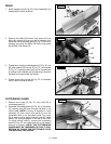
STAND
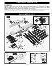
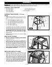
1. Assemble stand as shown in Fig. 5 using parts shown
in Fig. 4. The parts for the stand (as shown in Fig. 4)
are:
5. Two Top End Braces for Stand (11-3/4")
6. Two Top Side Braces for Stand (15-3/4")
7. Two Lower Side Braces for Stand (20-1/2")
8. Two Lower End Braces for Stand (16-1/2")
9. Four Legs for Stand
10. Four Feet for Stand Legs
To assemble, insert the 5/16-18x3/4" carriage head
bolts through legs and braces then place the 5/16"
flat washers on the bolts and secure with the 5/16-18
hex nuts. Only tighten nuts finger-tight at this time.
IMPORTANT: The top lips of two upper end braces
(5) Fig. 5, must fit on top of the top lips of two upper
side braces (6).
2. Assemble four rubber feet (10), to the bottom of each
leg (9) as shown.
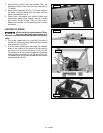
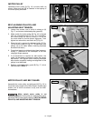
DUST CHUTE TO STAND
1. The front of the stand is indicated by switch opening
(B) Fig. 6, making the outfeed end of the stand (C)
and the infeed end (A).
2. Assemble dust chute (E) Fig. 6, to outfeed end of
stand (C) as shown. Align the four holes (D) Fig. 6, in
the dust chute with the four holes in the stand. Insert
a 5/16-18x3/4" carriage bolt through the hole in the
dust chute and stand. Place a 5/16" flat washer onto
the screw and thread a 5/16-18 hex nut onto the
screw. Repeat this process for the three remaining
holes in the dust chute and stand. Only tighten hex
nuts fingertight at this time.
For your own safety, do not connect the machine to the power source until the machine is
completely assembled and you read and understand the entire instruction manual.
10
9
7
8
8
6
5
7
6
5
Fig. 5
A
B
D
E
D
C
D
Fig. 6
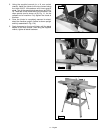
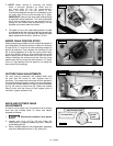
MOTOR AND SWITCH TO STAND
1. Assemble motor (B) Fig. 7, to the bottom of the
dust chute. Align the four holes (F) Fig. 7, in the dust
chute, with the four holes in the motor mounting
plate. Insert a 5/16-18x1¼"carriage bolt through
hole in dust chute and hole in motor mounting plate.
Place a 5/16" flat washer on screw and secure with
a 5/16-18 hex nut. Repeat this process for the three
remaining holes. Do not com plete ly tighten hex
nuts at this time as the motor must be adjusted
for proper alignment and belt tension later.
C
D
B
F
F
A
Fig. 7