


13 - English
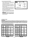
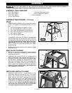
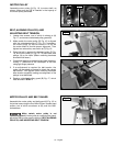
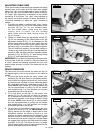
MOTOR PULLEY
Assemble motor pulley (A) Fig. 16, to motor shaft, as
shown. Make sure key (B) is inserted in the keyway of
the motor pulley and shaft.
BELT, ALIGNING PULLEYS, AND
ADJUSTING BELT TENSION
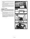
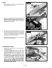
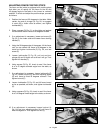
1. Loosen two screws, one of which is shown at (A)
Fig. 17, and remove cutterhead pulley guard (B)
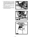
2. Make certain the motor pulley (D) Fig. 16, is aligned
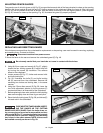
with the cutterhead pulley (C) Fig. 18. If necessary,
the motor pulley (D) can be moved in or out on
the motor shaft to provide proper alignment. Then
tighten two set screws, one shown at (C) Fig. 16.
3. Place the belt in groove of cutterhead pulley (C) Fig.
18, and motor pulley (D) Fig. 16. To place belt onto
pulleys, lift up on motor. (Motor mounting hardware
should still be loose.)
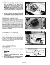
4. Correct belt tension is obtained when there is ap prox-
i mate ly 1" deflection at the centerspan of the belt
using light finger pressure.
5. If an adjustment is required for belt tension, the
motor can be raised or lowered to obtain the correct
belt tension. Then tighten motor mounting hardware
after ten sion is applied, making sure alignment of the
pulleys is not dis turbed.
6. Replace cutterhead pulley guard (B) Fig. 17, which
was removed in STEP 1.
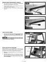
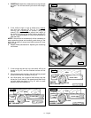
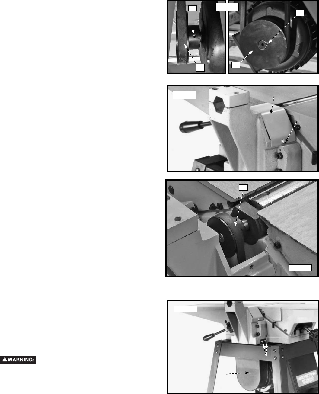
MOTOR PULLEY AND BELT GUARD
Assemble the motor pulley and belt guard (A) Fig. 19, to
the jointer base using the four M6x1x10mm cheese head
screws, two of which are shown at (B), and four M6.1
lockwashers.
Make certain motor pulley is not
contacting guard. If motor pulley is contacting the guard,
adjust the motor pulley, see the section "BELT, ALIGNING
PULLEYS, AND ADJUSTING BELT TENSION."
A
B
Fig. 19
B
A
Fig. 17
Fig. 16
A
B
C
Fig. 18
D
C