


17 - English
E
D
D
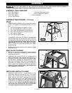
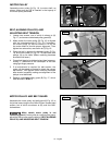
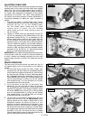
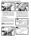
Fig. 41
4. CAREFULLY rotate the cutterhead by turning the belt
by hand. The knives should just touch the straight
edge.
5. If the knife is high or low at either end, slightly
turn the four screws (D) Fig. 41, in the knife
locking bar clockwise to loosen using the
wrench (E) supplied. Then adjust the height of
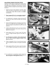
the knife by turning the knife raising screws (F)
Fig. 42, counterclockwise to lower and clockwise to
raise the knife.
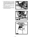
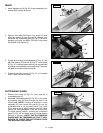
NOTE: If the knife is to be lowered it will be necessary to
wear protective gloves and carefully push down on the
knife with a piece of scrap wood after screws (F) have
been turned.
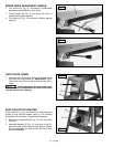
6. Repeat these procedures for adjusting the remaining
two knives.
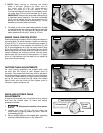
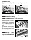
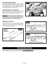
9. As a final check, run a piece of work slowly over the
knives for 6 to 8 inches. The wood should rest firmly
on both tables as shown in Fig. 45, with no open
spaces under the finished cut.
8. If the knives are set too high, the work will be gouged
at the end of the cut, as shown in Fig. 44.
7. If the knives are set too low, the result will be as
shown in Fig. 43, and the finished surface will be
curved.
KNIVES
SET TOO LOW
WORK
OUT-FEED
TABLE
IN-FEED TABLE
CUTTER
Fig. 43
KNIVES
SET TOO HIGH
IN-FEED TABLE
WORK
OUT-FEED
TABLE
CUTTER
Fig. 44
WORK
IN-FEED TABLE
CUTTER
OUT-FEED
TABLE
KNIVES AT
CORRECT HEIGHT
Fig. 45
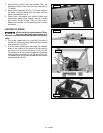
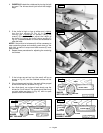
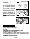
B
C
A
Fig. 40
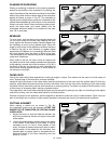
F
F
Fig. 42