


10
IP2046/IM
Nov 2006
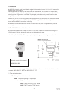
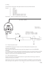
3.2 Mounting the transmitter above the liquid surface.
A 2” thread is provided to mount the transmitter.
The user should check the thread form, which will be either 2” BSPT (MSP400RH-B28) or 2” NPT
(MSP400RH-N28). The thread form is clearly marked on the hexagon of the transducer body.
Note : The MSP400 is designed to be mounted in a non-metallic fitting or flange. The use of metallic
fittings or flanges is not recommended.
To help installation, a bracket kit is available from Mobrey. This comprises a Stainless Steel angle bracket
and PVC threaded disc which may be used to mount the MSP400 on a gantry or other support over the
liquid level. Order part number MSP-BRK2 (BSP) or MSP-BRK3 (NPT). The bracket may be bolted to a
suitable cross member above the liquid surface.
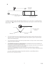
Ensure that the transmitter is perpendicular to the liquid surface to maximise the return echo size.
Check that the maximum liquid level will not encroach into the 0.45m blanking zone of the transmitter.
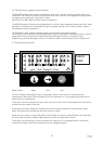
Note : To aid alignment, the echo size / signal strength can be displayed on the MCU900 control unit or
on the MSP400RH transmitter display. Refer to section 4 for details.
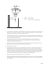
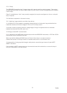
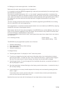
Use PTFE tape on the screw thread, tighten to hand tight + ¼ turn, using the Hexagon.
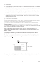
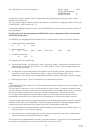
When installing on a vessel which has a nozzle or stand-off, and the transducer face does not protrude into
the vessel, note the dimensions in the diagram below and always ensure that the nozzle/vessel weld is
smooth and free from internal weld beads or other projections.
Use hexagon to
tighten to hand
tight + ¼ turn
DO NOT USE
HOUSING TO
TIGHTEN.
PTFE
(Teflon)
Max : 0,35m (14")
Min 0,15m (6")
Min :
R3,0mm (1/8")