


6
IP2046/IM
Nov 2006
3.0 Installation
Important safety notice : The MSP400 is designed for safe area use only, and must not be installed in a
hazardous area, even if the power is supplied through a barrier device.
General
a. Installation must be carried out by suitably trained personnel in accordance with the
applicable code of practice.
b. If the equipment is likely to come into contact with aggressive substances, it is the
responsibility of the user to take suitable precautions that prevent it from being adversely
affected, thus ensuring that the type of protection is not compromised.
Aggressive Substances – e.g. acidic liquids or gases that may attack metals or solvents that may
affect polymeric materials.
Suitable Precautions – e.g. regular checks as part of routine inspections or establishing from the
material’s data sheet that it is resistant to specific chemicals.
c. The equipment should only be cleaned with a damp cloth, do not use solvents.
d. The equipment is not intended to be repaired by the user and is to be replaced by an
equivalent certified unit. Repairs should only be carried out by the manufacturer or
approved repairer.
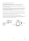
3.1 Location of the MSP400RH transmitter
Correct location of the transmitter is essential for the reliable operation of any ultrasonic level
measurement system.
Whilst the transmitter may be site tuned to deal with most application conditions, it is strongly
recommended that the following guidelines should be adopted wherever relevant.
3.1.1 General considerations
• The MSP400RH transmitter complies with the European Directive for Electro Magnetic Compatibility
(EMC) Class B.
It is not advisable to mount the transmitter in close proximity to a source of electrical noise such as a
variable speed drive or other high powered electrical device.
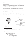
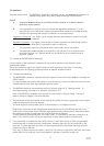
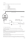
• The MSP400 should be mounted above the liquid surface using the “2” thread provided. To
facilitate mounting, a bracket kit is available. See Section 3.2.
Note : The MSP400 is designed to be mounted in a non-metallic fitting or flange. The use of
metallic fittings or flanges is not recommended.
• The transmitter should be mounted as near vertical as possible to ensure a good echo from the liquid
surface and maximum echo size received.
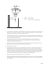
The beam angle (to the half power point) of the transmitter is 12 degrees inclusive.
Obstructions in the tank or well may generate echoes which can be confused with the real liquid
surface echo. Obstructions within the beam angle generate strong “false-echoes”; wherever possible,
the transmitter should be positioned such that false echoes are avoided.
To avoid detecting unwanted objects in the tank or well, it is advisable to maintain a distance of at
least 0.11m from the centre line of the transmitter for every metre range to the obstruction.
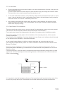
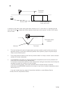
• If the transmitter is located near the side of the tank or well, there will be no false echo generated
provided the wall is smooth and free of protrusions. However, there will still be a reduction in the
echo size. To avoid large echo size loss, it is recommended that the transmitter never be mounted
closer than 0.3m to the wall.
Fatty, dirty or viscous liquids can cause a “scum line” to build-up on the tank or well wall. Avoid false
echoes from this by enabling “scum line prevention” software in the MCU control unit.