


20
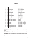
VRS OIL SOLENOID OUTPUT – Used in VRS retrofit applications where an oil solenoid is installed in the oil line.
COMP MOTOR STARTER AUXILIARY CONTACT – This input looks for a feedback signal from the compressor starter,
confirming that the compressor starter is energized.
HIGH LEVEL SHUTDOWN INPUT – This input must be energized in order for the compressor to operate. If de-ener-
gized, the compressor will shut down and issue a high level trip.
OIL LEVEL FLOAT SWITCH #1 INPUT – Used for Cool Compression.
OIL LEVEL FLOAT SWITCH #2 INPUT – Used for Cool Compression.
LOCAL/REMOTE SELECT INPUT – This input enables or disables remote I/O control. Energizing this input enables
the Remote Capacity Increase and Remote Capacity Decrease inputs.
REMOTE START/STOP INPUT – If the compressor is enabled for remote I/O control, this input is enabled. Energiz-
ing this input will issue a start for the compressor as long as it is available to run. De-energizing this input stops
the compressor.
REMOTE CAPACITY INCREASE INPUT – If the compressor is enabled for remote I/O control, this input is enabled.
Operational only when the compressor is running. Energizing this input will increase the slide valve position.
The slide valve will continuously increase as long as this input is energized. The slide valve will not increase when
this input is de-energized.
NOTE: The scan interval on the remote increase and decrease modules is approximately ONE SECOND.
Please take that into account when developing a control scheme using the remote increase and remote
decrease modules for compressor control.
REMOTE CAPACITY DECREASE INPUT – If the compressor is enabled for remote I/O control, this input is enabled.
Operational only when the compressor is running. Energizing this input will decrease the slide valve position.
The slide valve will continuously decrease as long as this input is energized. The slide valve will not decrease
when this input is de-energized.
CONDENSER STEP #1 OUTPUT – This output is enabled when condenser control option is selected. A condenser
fan or pump will be turned on or off by this output.
CONDENSER STEP #2 OUTPUT – This output is enabled when condenser control option is selected. A condenser
fan or pump will be turned on or off by this output.
CONDENSER STEP #3 OUTPUT – This output is enabled when condenser control option is selected. A condenser
fan or pump will be turned on or off by this output.
CONDENSER STEP #4 OUTPUT – This output is enabled when condenser control option is selected. A condenser
fan or pump will be turned on or off by this output.
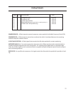
AUXILIARY #1 thru #8 INPUT – Optional inputs that can be configured as an alarm or trip. Typically connected to
external switched devices.