


66
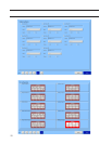
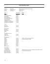
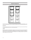
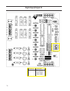
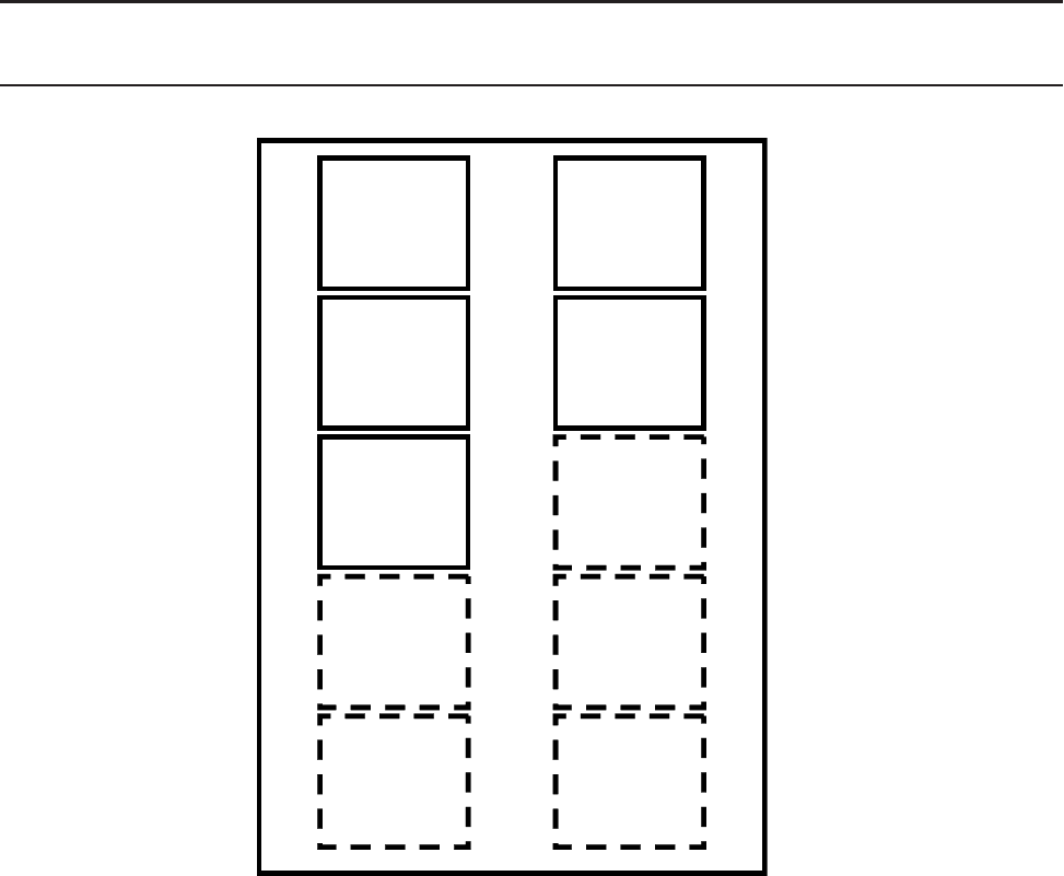
The illustration above shows the position and type of the digital and analog input/output (I/O) boards. It is im-
portant to install the boards as shown in this illustration and configure them as show in the following illustrations.
DIPSWITCHES
Each board has a dipswitch which sets its communications address so that it can communicate with the CPU board.
The dipswitch settings must be correct, or the I/O will not function.
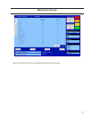
JUMPERS
Jumpers are required on the analog boards to configure them for the type of sensors used. The jumper table for
the analog board shows the optional jumper configurations for sensors other than the default Vilter standard. If a
different sensor is to be used, the jumpers on the analog board need to be changed. In addition, the configuration
for this sensor must be changed in the Instrument Calibration screen. The following illustrations show the Vilter
default configurations for the Vission 20/20.
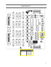
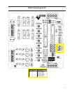
DIGITAL
OUT #1
(ADDRESS 1)
Digital & Analog Boards
DIGITAL
OUT #2
(ADDRESS 2)
DIGITAL
IN
(ADDRESS 3)
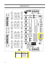
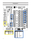
DIGITAL
I/O #1
(ADDRESS 4)
DIGITAL
I/O #2
(ADDRESS 5)
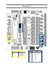
ANALOG
IN #1
(ADDRESS 6)
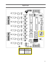
ANALOG
IN #2
(ADDRESS 7)
ANALOG
IN #3
(ADDRESS 8)
ANALOG
IN #4
(ADDRESS 9)
ANALOG
OUT
(ADDRESS 10)