


49
Slide Valve Operation
The slide valve actuator is a gear-motor with a posi-
tion sensor. The motor is powered in the forward
and reverse directions from the main computer in
the control panel. The position sensor tells the main
computer the position of the slide valve. The main
computer uses the position and process information
to decide where to move the slide valve next.
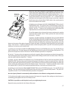
The position sensors works by optically counting
motor turns. On the shaft of the motor is a small
aluminum “photochopper”. It has a 180 degree
fence that passes through the slots of two slotted
optocouplers. The optocouplers have an infrared
light emitting diode (LED) on one side of the slot and
a phototransistor on the other. The phototransistor
behaves as a light controlled switch. When the pho-
tochopper fence is blocking the slot, light from the
LED is prevented from reaching the phototransistor
and the switch is open. When photochopper fence
is not blocking the slot, the switch is closed.
As the motor turns, the photochopper fence al-
ternately blocks and opens the optocoupler slots,
generating a sequence that the position sensor mi-
crocontroller can use to determine motor position
by counting. Because the motor is connected to the
slide valve by gears, knowing the motor position
means knowing the slide valve position.
During calibration, the position sensor records the
high and low count of motor turns. The operator
tells the position sensor when the actuator is at the
high or low position with the push button. Refer to
the calibration instructions for the detailed calibra-
tion procedure.
The position sensor can get “lost” if the motor is
moved while the position sensor is not powered. To
prevent this, the motor can only be moved electri-
cally while the position sensor is powered. When
the position sensor loses power, power is cut to the
motor. A capacitor stores enough energy to keep
the position sensor circuitry alive long enough for
the motor to come to a complete stop and then save
the motor position to non-volatile EEPROM memory.
When power is restored, the saved motor position
is read from EEPROM memory and the actuators
resumes normal function
This scheme is not foolproof. If the motor is moved
manually while the power is off or the motor brake
has failed, allowing the motor to free wheel for too
long after the position sensor looses power, the
actuator will become lost.
A brake failure can sometimes be detected by the
position sensor. If the motor never stops turning
after a power loss, the position sensor detects this,
knows it will be lost, and goes immediately into
calibrate mode when power is restored.