


65
Vission 20/20 Troubleshooting Guide
Before applying power to the Vission 20/20 control panel, all wiring to the panel should be per the National
Electrical Code (NEC). Specifically check for proper voltage and that the neutral is grounded at the source. An
equipment ground should also be run to the panel.
In the event of a problem with the Vilter Vission 20/20, the help screen, along with your electrical drawings will
help determine the cause.
PROBLEM and POSSIBLE SOLUTION
1. Vission 20/20 does not boot up, no lights light on any boards.
a) Check to make sure 120VAC is run to circuit breaker CB1 located on the terminal strip. The neutral should be
brought to any “N” terminal on the terminal strip.
b) Check to insure circuit breaker CB1’s switch is flipped in the ON direction.
c) Use a voltmeter to insure 120VAC is being applied to the power supply, located on the door. Check that 120 volts
is present at the F1 fuse on the power supply, located on the front of the door. If all of the above are OK, the power
supply may be bad. To test the power supply, check DC voltages at the power supply output. If proper voltages
are not found at these test points, the power supply may be faulty.
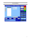
2. Vission 20/20 appears to be booted, lights are lit on the boards, but no touchscreen display is evident.
a) Remove power COMPLETELY from the Vission 20/20 and restart the controller.
WARNING! The inverter board creates a high rms voltage to drive the backlight - it can exceed
1500VAC. Use extreme caution and insure that voltage has been removed from the board
before physical inspection. Visually check cable connections located on the LCD inverter board.
This board is located inside the door on the LCD touch screen back plane next to the single
board computer. Physically inspect board to insure that all cable connectors are connected tightly
to the board connectors. If these are inserted correctly, the problem could be a bad LCD inverter board or a com-
ponent failure.
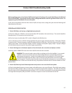
3. Vission 20/20 boots up but all data temperatures and pressures are zeroed and do not update.
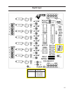
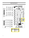
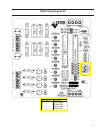
a) Check Analog board jumpers to insure proper node addresses are set up on all boards. Physically inspect power
and communication jumper cables to insure they are inserted properly and completely. Two LEDs on all boards
show the status of the communications for the board. LED1 is on when a command is received at the board from
the single board computer (SBC), and LED2 is on when a response is sent from the board to the SBC.