


11
English
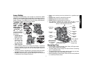
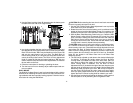
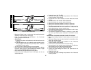
3. Use the Base Leveling Knob (B) located under the battery pack
to stabilize the tool and aid in rough leveling.
4. In a plumb orientation the laser can be positioned over a mark and
fine adjustments of the laser position can be made using the Base
Rack 'N Pinion Knobs.
TIP:
It may be helpful to turn the power ON
and spin the rotary head to set your mark. The Base Rack 'N
Pinion Locking Knob (D) is a wing nut style knob that will lock and
unlock the sliding base bracket. The Rack 'N Pinion Adjustment
Knob (C) rotates to slide the tool forward and back.
TIP:
You may
need to hold the laser base down while adjustments are made to
the tool while on the floor.
5. Follow the instructions for leveling or plumbing the laser.
6. Turn the laser on if not on already; adjust rotation speed and con-
trols as needed.
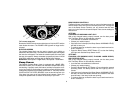
WALL MOUNT
The DW073 Cordless Rotary Laser has been designed with a built-in
Wall Mount for attaching the tool to wall track to aid in acoustical ceil-
ing installation and other specialty leveling projects. Follow the instruc-
tions below for using the Wall Mount.
A
B
A
D
C
CAUTION: Before attaching the laser level to wall track ensure that
the track is properly secured to the wall.
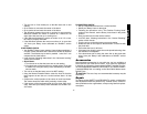
1. Use the Two-Position Pivoting Head Adjustment Lever to pivot the
laser head into a plumb orientation.
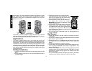
2. Rotate the entire tool so that the battery pack is positioned at the
bottom of the tool and the Wall Mount Clamp is in position to be
attached to the wall track. See illustration at left for proper set-up.
3. With the Base Plate Measuring Scale facing you, rotate the Wall
Mount Clamp Locking Knob (A) towards you to open the clamp
jaws. Position the clamp jaws around the wall track and rotate the
Wall Mount Clamp Locking Knob away from you to close the
clamp jaws shut on the track. Ensure that the Wall Mount Clamp
Locking Knob is securely locked before proceeding.
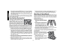
CAUTION: Always use a ceiling wire hanger or equivalent materi-
al, in addition to the wall mount clamp, to help secure the laser level
while mounting it to a wall. Thread the wire through the holes in the roll
cage above the Rack 'N Pinion Adjustment Knob (C) or above the
Rack 'N Pinion Locking Knob (D). Additionally, screws or nails can be
used to fasten the tool directly to the wall as a back up. Screw/Nail
holes (B) are located in the Base Plate next to the Base Plate
Measuring Scales.
4. The tool can be adjusted up and down to the desired offset height
for working. To change the height, loosen the Rack 'N Pinion
Locking Knob (D) located to the left of the laser head.
TIP:
You
may need to support the weight of the tool while the Rack 'N
Pinion Locking Knob is loosened. Turn the Rack 'N Pinion
Adjustment Knob (C) located to the right of the laser head to move
the laser level up and down to set your height. Use the Base Plate
Measuring Scale to pinpoint your mark.
TIP:
It may be helpful to
turn the power ON and spin the rotary head to set your height.
Once you have positioned the laser at your desired offset height,
tighten the Rack 'N Pinion Locking Knob to maintain your mark.
5. Use the Base Leveling Knob (behind the battery) at the bottom of
the base plate to aid in positioning the tool against the wall.