


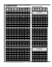
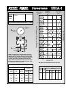
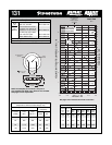
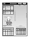

Force Table (Use for Airstroke
®
actuator design)
Volume
Pounds Force
Assembly @ 100
Height PSIG @20 @40 @60 @80 @100
(in.) (in
3
) PSIG PSIG PSIG PSIG PSIG
3.0 14 118 235 356 475 593
Dynamic Characteristics at 3.0 in. Design Height
(Required for Airmount isolator design only)
Volume @ 100 PSIG = 14 in
3
Gage Spring
Pressure Load Rate
(PSIG) (lbs.) (lbs./in.)
40 235 191 199.52 3.33
60 356 274 169.93 2.83
80 475 352 161.74 2.70
100 593 458 165.29 2.75
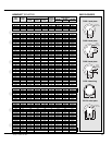
Description
Assembly Order No.
Blind nut, 1/8 NPT, WO2-358-3003
brass stud
Assembly weight ........................................................ 0.5 lbs.
Force to collapse to minimum height (@ 0 PSIG)......... 20 lbs.
Natural
Frequency
CPM HZ
12
10
8
6
4
2
0
24
20
16
12
8
4
0
4
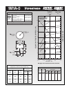
MAX. HT. MIN. HT.
3 2 1.5
Volume
100 Psig
20 Psig
40 Psig
60 Psig
120 Psig
100
Psig
80 Psig
Do not use
Airstroke
in shaded
area without
consulting
Firestone
2.53.5
CONSULT FIRESTONE
BEFORE USING AS
AIRMOUNT
RECOMMENDED
AIRMOUNT
DESIGN HEIGHT
3.0 INCHES
Static Data
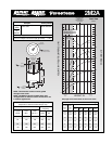
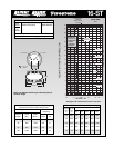
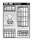
B3940
HEIGHT IN.
1M1A
-
1
35
3.4 MAX O.D.
AT 60 PSIG
HEIGHT
5/16-18
THREADED HOLE
(3/8 DEEP)
5/8-11
1.00
2.40 DIA.
1/8 NPT
AIR INLET
2.88 DIA.
3-5 TURNS
30-50 IN. LBS.
TORQUE
100-130 IN. LBS.
TORQUE
See page 12 for instructions on how to use chart.
NOTE: The dotted line on the static data chart shows
the force capabilities of the 1M1A-1 when attaching an
additional 0.5 inch pedestal, provided by the customer,
to the base of the air spring. If an additional pedestal is
not used, the air spring will behave as the solid line
depicts. Without a pedestal the rubber part will contact
the ground at the height of 2.1 inches and could cause
the rubber part to wear prematurely.
VOLUME (WITHOUT BUMPER) CU IN.
FORCE LBS x 100
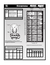
Style
1M1A-1
Two
Ply
Bellows