


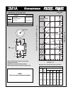
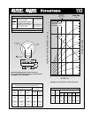
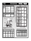
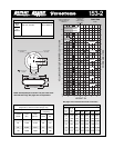

Dynamic Characteristics at 4.5 in. Design Height
(Required for Airmount isolator design only)
Volume @ 100 PSIG = 192 in
3
Gage Spring
Pressure Load Rate
(PSIG) (lbs.) (lbs./in.)
40 1,180 1,008 174 2.89
60 1,750 1,417 169 2.81
80 2,350 1,846 166 2.77
100 3,010 2,257 163 2.71
Natural
Frequency
CPM HZ
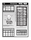
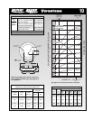
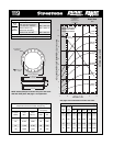
6 5 4 3 2
MAX. HT. MIN. HT.
5
4
3
2
1
100 Psig
80 Psig
40 Psig
20 Psig
60 Psig
120 Psig
Volume
100 Psig
2
1
Do not use Airstroke in
shaded area without
consulting Firestone
Bumper Contact
(3.0)
RECOMMENDED
AIRMOUNT
DESIGN HEIGHT
4.5 INCHES
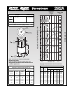
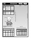
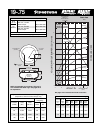
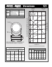
Static Data
1115
HEIGHT IN.
115
44
HEIGHT
OPTIONAL
BUMPER
*(1.50 FOR 3/4)
10.1 MAX O.D.
AT 100 PSIG
6.31 DIA.
3/8-16 BLIND NUTS
(5/8 DEEP)
3.50
1/4 or 3/4 NPT
AIR INLET
15-20 FT. LBS.
TORQUE
1.75*
NOTE: A bead plate part is shown. This part is
also available with bead rings. See pages 8-10
for explanation.
See page 12 for instructions on how to use chart.
VOLUME (WITHOUT BUMPER) CU IN. x 100
FORCE LBS x 1000
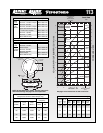
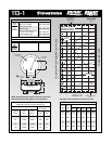
Description
Assembly Order No.
Blind nuts, 1/4 NPT WO1-358-7460
Blind nuts, 1/4 NPT
rubber bumper WO1-358-7459
Blind nuts, 3/4 NPT WO1-358-7465
Blind nuts, 3/4 NPT
rubber bumper WO1-358-7458
Countersunk steel bead rings,
1
5
/8
bolts, nuts, washers
WO1-358-7469
Blind nuts, 3/4 NPT
both ends (centered) WO1-606-7115
Rubber bellows only WO1-358-0118
Assembly weight ........................................................ 5.5 lbs.
Force to collapse to minimum height (@ 0 PSIG)......... 8 lbs.
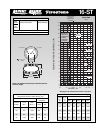
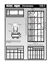
Style
115
Two
Ply
Bellows
Blind nuts, 1/4 NPT WO1-358-7650
Blind nuts, 3/4 NPT WO1-358-7649
Style
124
High
Strength
Bellows
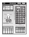
Force Table (Use for Airstroke
®
actuator design)
Volume
Pounds Force
Assembly @ 100
Height PSIG @20 @40 @60 @80 @100
(in.) (in
3
) PSIG PSIG PSIG PSIG PSIG
5.0 207 460 840 1,290 1,730 2,270
4.0 173 740 1,440 2,150 2,870 3,640
3.0 130 890 1,760 2,650 3,550 4,520