


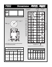
Description
Assembly Order No.
Blind nuts, 1/4 NPT WO1-358-5310
Blind nuts, 1/4 NPT, bumper WO1-358-5311
Blind nuts, 3/4 NPT WO1-358-5305
Blind nuts, 3/4 NPT, bumper WO1-358-5306
Countersunk steel bead ring
1
3
/4 bolts, nuts, washers WO1-358-5307
Assembly weight ........................................................ 6.5 lbs.
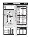
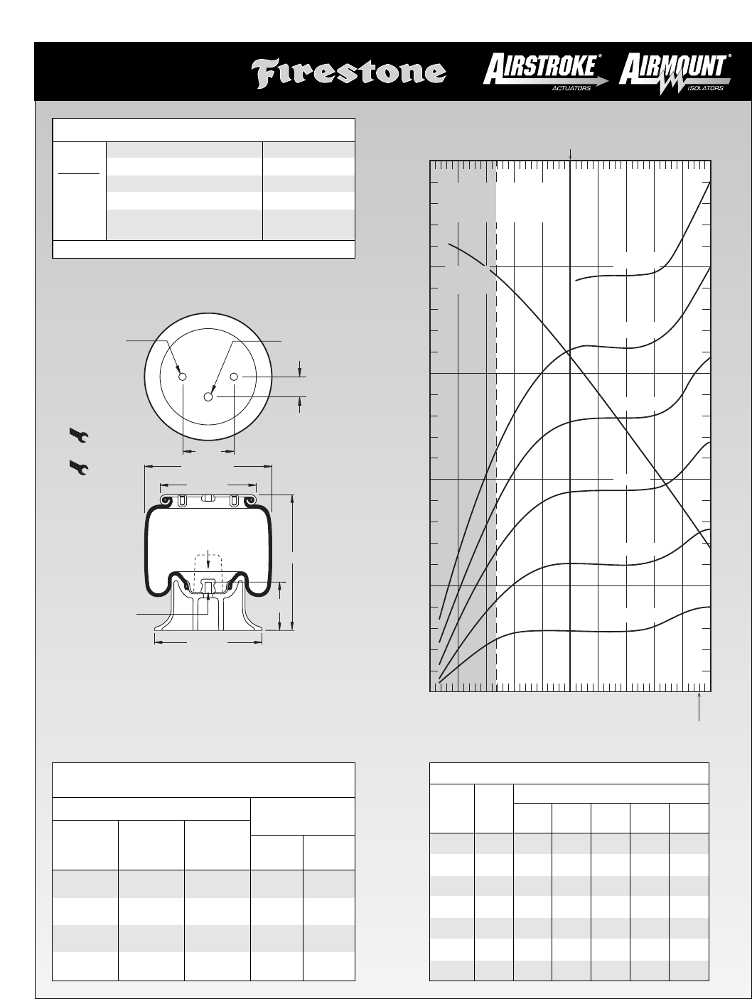
9 7 5
MAX. HT.
4
3
2
1
0
MIN. HT.
60 Psig
20 Psig
100 Psig
80 Psig
40 Psig
120 Psig
Volume
100 Psig
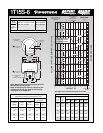
Do not use Airstroke in
shaded area without
consulting Firestone
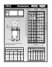
4
3
2
1
0
15 13 11
BUMPER CONTACT
5.4 IN.
CONSULT FIRESTONE
BEFORE USING AS
AIRMOUNT
RECOMMENDED
AIRMOUNT
DESIGN HEIGHT
10.0 INCHES
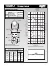
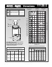
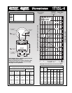
Static Data
3019
HEIGHT IN.
9.1 MAX O.D.
AT 100 PSIG
HEIGHT
7.25 DIA.
3/8-16 BLIND NUTS
(5/8 DEEP)
1/4 OR 3/4 NPT
AIR INLET
3.50
1.75*
OPTIONAL
BUMPER
*(1.50 FOR 3/4)
3.16
6.31 DIA.
1/2-13 THREADED HOLE
(3/4 DEEP)
15-20 FT. LBS.
TORQUE
25-30 FT. LBS.
TORQUE
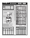
NOTE: Bellows will not compress properly with less
than 10 PSIG internal pressure.
NOTE: A bead plate part is shown. This part is also
available with a bead ring. Bolts are not included.
See pages 8-10 for explanation.
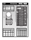
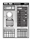
See page 12 for instructions on how to use chart.
VOLUME (WITHOUT BUMPER) CU IN. x 100
FORCE LBS x 1000
Style
1T14C-1
Two
Ply
Bellows
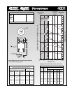
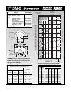
Dynamic Characteristics at 10.0 in. Design Height
(Required for Airmount isolator design only)
Volume @ 100 PSIG = 314 in
3
Gage Spring
Pressure Load Rate
(PSIG) (lbs.) (lbs./in.)
40 1,210 250 85 1.42
60 1,880 398 86 1.44
80 2,540 535 86 1.43
100 3,220 658 85 1.41
Natural
Frequency
CPM HZ
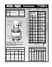
Force Table (Use for Airstroke
®
actuator design)
Volume
Pounds Force
Assembly @ 100
Height PSIG @20 @40 @60 @80 @100
(in.) (in
3
) PSIG PSIG PSIG PSIG PSIG
12.0 376 540 1,010 1,530 2,040 2,600
11.0 347 570 1,160 1,770 2,380 3,010
10.0 314 590 1,210 1,880 2,540 3,220
9.0 280 590 1,190 1,890 2,570 3,240
8.0 246 580 1,200 1,890 2,570 3,240
7.0 211 620 1,240 1,920 2,600 3,300
6.0 176 740 1,380 2,060 2,790 3,530
86
1T14C-1