


55
7 6 5 4
MAX. HT. MIN. HT.
22
21
20
19
18
17
16
15
14
13
12
11
10
9
8
7
6
5
4
3
2
1
11
10
9
8
7
6
5
4
3
2
1
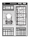
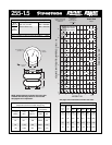
2.8
60 Psig
40 Psig
20 Psig
Volume
100 Psig
80 Psig
100 Psig
120 Psig
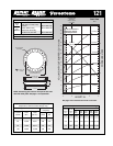
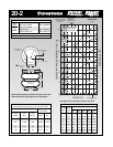
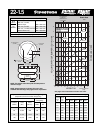
Do not use Airstroke in
shaded area without
consulting Firestone
RECOMMENDED
AIRMOUNT
DESIGN HEIGHT
5.5 INCHES
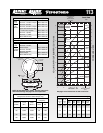
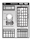
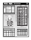
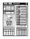
Static Data
8828
HEIGHT IN.
25
HEIGHT
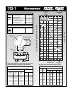
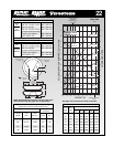
3/8-16 BLIND NUTS
(5/8 DEEP)
6.4 MAX O.D.
AT 100 PSIG
1.75
4.50 DIA.
1/4 NPT
AIR INLET
15-20 FT. LBS.
TORQUE
NOTE: A bead plate part is shown. This part is also
available with bead rings. Bolts are not included.
See pages 8-10 for explanation.
See page 12 for instructions on how to use chart.
VOLUME (WITHOUT BUMPER) CU IN. x 10
FORCE LBS x 100
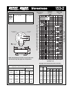
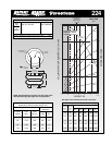
Dynamic Characteristics at 5.5 in. Design Height
(Required for Airmount isolator design only)
Volume @ 100 PSIG = 82 in
3
Gage Spring
Pressure Load Rate
(PSIG) (lbs.) (lbs./in.)
40 430 329 164 2.73
60 670 477 158 2.63
80 910 616 154 2.57
100 1,180 757 151 2.51
Natural
Frequency
CPM HZ
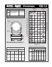
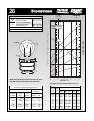
Description
Assembly Order No.
Blind nuts, 1/4 NPT WO1-358-7025
Blind nuts, 3/4 NPT WO1-358-7047
Blind nuts, 1/4 NPT both ends WO1-358-7035
3/4 NPT both ends
(no blind nuts) WO1-606-7025
Socket head aluminum bead
rings (bolts, nuts, washers not
included, use cap screws)
WO1-358-0030
3/4 NPT (only) upper plate,
blind nuts lower plate WO1-358-7030
Rubber bellows only
(no girdle hoop) WO1-358-0025
Assembly weight ........................................................ 3.8 lbs.
Force to collapse to minimum height (@ 0 PSIG)....... 30 lbs.
Style
25
Two
Ply
Bellows
Force Table (Use for Airstroke
®
actuator design)
Volume
Pounds Force
Assembly @ 100
Height PSIG @20 @40 @60 @80 @100
(in.) (in
3
) PSIG PSIG PSIG PSIG PSIG
5.0 75 240 520 800 1,080 1,380
4.0 58 310 660 990 1,330 1,690
3.0 39 360 750 1,130 1,530 1,930