


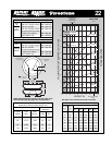
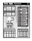
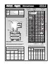
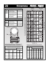

Force Table (Use for Airstroke
®
actuator design)
Volume
Pounds Force
Assembly @ 100
Height PSIG @20 @40 @60 @80 @100
(in.) (in
3
) PSIG PSIG PSIG PSIG PSIG
11.0 1,510 1,540 3,180 4,930 6,730 8,550
10.0 1,410 1,810 3,710 5,730 7,760 9,790
9.0 1,298 2,040 4,150 6,430 8,570 10,780
8.0 1,177 2,240 4,530 7,050 9,290 11,690
7.0 1,048 2,400 4,850 7,570 10,030 12,620
6.0 910 2,530 5,140 8,000 10,670 13,440
5.0 764 2,620 5,370 8,310 11,100 13,990
4.0 615 2,690 5,490 8,490 11,330 14,280
Dynamic Characteristics at 10.5 in. Design Height
(Required for Airmount isolator design only)
Volume @ 100 PSIG = 1,462 in
3
Gage Spring
Pressure Load Rate
(PSIG) (lbs.) (lbs./in.)
40 3,460 989 100 1.67
60 5,350 1,437 97 1.62
80 7,280 1,850 95 1.58
100 9,210 2,247 93 1.55
Description
Assembly Order No.
Blind nuts, 1/4 NPT WO1-358-6800
Blind nuts, 1/4 NPT, rubber
bumper WO1-358-6801
Blind nuts, 3/4 NPT WO1-358-9529
Assembly weight ....................................................... 18.2 lbs
Force to collapse to minimum height (@ 0 PSIG)....... 35 lbs.
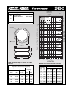
Natural
Frequency
CPM HZ
MAX. HT. MIN. HT.
18
17
16
15
14
13
12
11
10
9
8
7
6
5
4
3
2
1
80 Psig
100 Psig
14 12 10
Bumper Contact
(4.8)
120 Psig
8 6 4
18
17
16
15
14
13
12
11
10
9
8
7
6
5
4
3
2
1
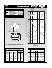
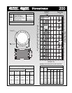
Do not use Airstroke in
shaded area without
consulting Firestone
Volume
100 Psig
40 Psig
60 Psig
20 Psig
RECOMMENDED
AIRMOUNT
DESIGN HEIGHT
10.5 INCHES
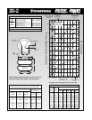
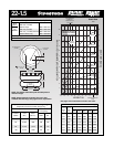
Static Data
3931
HEIGHT IN.
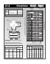
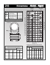
21-2
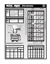
64
HEIGHT
OPTIONAL
BUMPER
3/8-16 BLIND NUTS
(5/8 DEEP)
16.0 MAX O.D.
AT 100 PSIG
6.25
11.31 DIA.
15-20 FT. LBS.
TORQUE
6.25
1/4 OR 3/4 NPT
AIR INLET
See page 12 for instructions on how to use chart.
VOLUME (WITHOUT BUMPER) CU IN. x 100
FORCE LBS x 1000
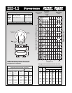
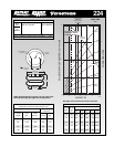
Style
21-2
Two
Ply
Bellows
NOTE: A bead plate part is shown. This part is also
available with bead rings. See pages 8-10 for explanation.
NOTE: The bellows extends beyond the bead plates at
minimum height.