


59
MAX. HT. MIN. HT.
6
5
4
3
2
1
6
5
4
3
2
1
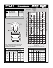
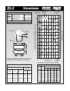
60 Psig
80 Psig
100 Psig
20 Psig
Do not use Airstroke in
shaded area without
consulting Firestone
120 Psig
40 Psig
Volume
100 Psig
11 10 9 8 7 6 5 4 3
Bumper Contact
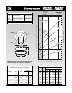
(4.2)
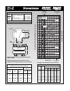
RECOMMENDED
AIRMOUNT
DESIGN HEIGHT
8.5 INCHES
Static Data
1820
HEIGHT IN.
20
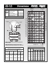
HEIGHT
OPTIONAL
BUMPER
*(1.50 FOR 3/4)
3/8-16 BLIND NUTS
(5/8 DEEP)
9.9 MAX O.D.
AT 100 PSIG
1.75
*
6.31 DIA.
1/4 OR 3/4 NPT
AIR INLET
15-20 FT. LBS.
TORQUE
3.50
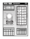
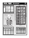
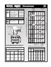
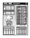
NOTE: A bead plate part is shown. This part is also avail-
able with bead rings. See pages 8-10 for explanation.
See page 12 for instructions on how to use chart.
VOLUME (WITHOUT BUMPER) CU IN. x 100
FORCE LBS x 1000
Dynamic Characteristics at 8.5 in. Design Height
(Required for Airmount isolator design only)
Volume @ 100 PSIG = 376 in
3
Gage Spring
Pressure Load Rate
(PSIG) (lbs.) (lbs./in.)
40 990 414 121 2.02
60 1,540 615 119 1.98
80 2,130 820 116 1.94
100 2,720 996 114 1.89
Natural
Frequency
CPM HZ
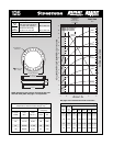
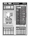
Description
Assembly Order No.
Blind nuts, 1/4 NPT WO1-358-6910
Blind nuts, 1/4 NPT, bumper WO1-358-6911
Blind nuts, 3/4 NPT WO1-358-6900
Blind nuts, 3/4 NPT, bumper WO1-358-6901
Countersunk steel bead rings,
1
3
/4
bolts, nuts, washers
WO1-358-6923
Rubber bellows only WO1-358-7901
Assembly weight ........................................................ 7.5 lbs.
Force to collapse to minimum height (@ 0 PSIG)....... 14 lbs.
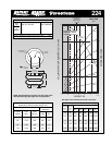
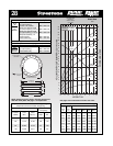
Style
20
Two
Ply
Bellows
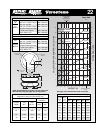
Blind nuts, 1/4 NPT WO1-358-7080
Blind nuts, 3/4 NPT WO1-358-7119
Style
202
High
Strength
Bellows
Force Table (Use for Airstroke
®
actuator design)
Volume
Pounds Force
Assembly @ 100
Height PSIG @20 @40 @60 @80 @100
(in.) (in
3
) PSIG PSIG PSIG PSIG PSIG
9.0 390 420 850 1,330 1,850 2,380
8.0 360 550 1,120 1,730 2,390 3,030
7.0 325 660 1,330 2,090 2,830 3,570
6.0 284 760 1,520 2,390 3,180 4,030
5.0 239 840 1,680 2,610 3,510 4,430
4.0 190 920 1,830 2,810 3,790 4,790