


307–758 17
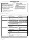
TYPE
OF PROBLEM
WHAT
T
O CHECK
If check is OK, go to next check
WHA
T T
O DO
When check is not OK refer to this column
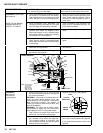
1
.
Check
leads from bridge (308) to motor to be
sure they are securely fastened and properly
mated.
1. Replace loose terminals; crimp to leads.
Be sure male terminal blades are straight
and
firmly connected to mating part.
2. Check G1 and G2 connections between cir-
cuit
board (72) and bridge (308) for damage or
loose
terminals.
2. Clean circuit board male terminals. Re-
place loose or damaged terminals. Se-
curely
reconnect leads.
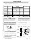
3. Check for loose motor brush lead connec-
tions
and terminals. See page 25.
3. Tighten
terminal
screws. Replace brushes
if
leads are damaged. See page 25.
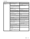
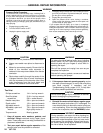
4. Check brush length which should be 1/2”
minimum.
See page 25.
NOTE:
The brushes do not wear at the same
rate on both sides of the motor. Check both
brushes.
4. Replace
brushes. See page 25.
5. Check for broken or misaligned motor brush
springs. Rolled portion of spring must rest
squarely
on top of brush. See page 25.
5. Replace spring if broken. Realign spring
with
brush. See page 25.
6. Check motor brushes for binding in brush
holders.
See page 25.
6. Clean
brush holders. Remove carbon
with
small cleaning brush. Align brush leads
with
slot in brush holder to
assure free verti
-
cal
brush movement.
7. Check motor armature commutator for burn
spots, gouges and extreme roughness. Re-
move motor cover and brush inspection
plates
to check. See page 25.
7. Remove
motor and have
motor shop resur
-
face
commutator if possible.
See page 34.
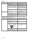
8. Check
motor armature for
shorts using arma
-
ture
tester (growler) or perform spin test. See
page
22.
8.
Replace motor
. See page 34.
9. Check bridge (308) by substituting with a
good bridge or performing bridge test. See
page
23.
CAUTION:
Do not perform this check until
motor armature is determined to be good. A
bad
motor armature will immediately burn out
a
good bridge.
9.
Replace bridge. See page 23.
Condition
B
(continued)
Both
lamps of
f
1. Check
circuit breaker (309) button
to be sure
it
has not popped up.
1. Depress
button to
reset. If circuit breaker or
fuse continues to open, see “Electrical
Short”,
page 21.
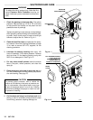
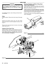
REFER TO THE WIRING
DIAGRAM ON P
AGE 18
TO IDENTIFY TP POINTS.
2. Check power supply cord (311). Disconnect
TP6 female (neutral) and TP1 female and
connect volt meter to these leads. Plug in
sprayer. Meter should read 105 to 125 VAC.
Unplug sprayer
. Reconnect TP1.
2. Replace
power supply cord. See page 26.
NOTE:
Connect the volt meter
to the terminal not the wire
which
you disconnect from the
terminal.
3. Check
ON/OFF switch (303). Disconnect
TP2
and connect volt meter to TP6 female and
TP2
male.
Plug in sprayer and turn
ON
. Meter
should
read 105
to 125 V
AC. T
urn of
f and un
-
plug sprayer
. Reconnect TP2.
3.
Replace ON/OFF switch. See page 26.
4. Check jumper wire (306). Disconnect TP3
and connect volt meter to TP6 female and
TP3
female. Plug in sprayer and turn on. Me
-
ter
should read 105 to 125 V
AC. T
urn of
f and
unplug sprayer
. Reconnect TP3.
4.
Replace jumper wire. See page 26.
5. Check
circuit breaker (309). Connect volt me
-
ter to TP6 female and TP4. Plug in sprayer
and turn ON. Meter should read 105 to 125
VAC.
T
urn of
f and unplug sprayer
.
5.
Replace circuit breaker
. See page 27.
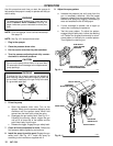
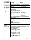
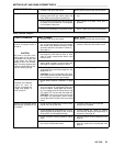
MOTOR
WON’T OPERA
TE
Diagnosing circuit board
indicator
lamps.
The
normal
condition
is red
lamp on, clear
lamp
on when board is telling
pump
to run.
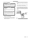
Follow Pressure Relief Pro-
cedure Warning. Remove
gun
from hose. Remove
pres
-
sure control cover. Check for
faulty condition of circuit
board
lamps.
Condition A
Both
lamps on; pump
won’t
operate and motor is not
running